IF630
System Operation/Installation 5/26/01
___________________________________________________________________________________________
Rev 3.0
19
Main Power Supply
The main power supply (p/n 30887) is a combination 8 amp system power supply
and battery charger. The standard battery charger is sized to maintain up to 50
Ah batteries. The battery charger is designed to operate during set intervals
extending the battery life and a battery charger is capable of operating with lead
acid batteries.
Installation
Diagram
Refer to D-W1145, Wiring, IF630 Analog Addressable System (or D-W1160 for
IF630-126) for installation and cable connections.
Specifications
Input Voltage
120 VAC 50/60 Hz 3 amps Max.
Operating Temperature 0 to +49 degrees C
Humidity
85% non-condensing
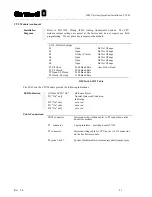
Interconnects
24 VAC
(2) secondary transformer connection
C+, C-
Connection (Red, Black) to Filter Capacitor
B+, B-
(Red, Black) connections to Battery
J4 connector
Interconnects to J2 on the analog addressable
module
J3 connector
Interconnects to J16 on bus driver module
J2 connector
Interconnects to J12 on bus driver module (5V,
12V, and 24V supervision)
Operators Display
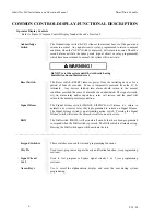
The Operators Display (OD) is the main interface to system. The display
provides the user with all necessary switches, keys and annunciation points to
maintain and monitor the system. Alarm, supervisory and trouble conditions are
indicated by dedicated LED's and the internal sounder. The system's operating
status is shown on the alphanumeric display. LED annunciation is also provided
for AC power, PreAlarm, (2) signal circuits, City Tie connection and Bypass.
The alphanumeric keypad provides user access for programming and password
entry.
The alphanumeric display contains a 4 x 40 character backlit display. To regulate
the contrast of the alphanumeric LCD display, adjust the potentiometer R29
located (solder side of the display board - lower left hand corner) - see drawing D-
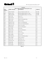
W1145). The card location identification number is " 0 " (see above Table I-1).
Installation
Diagram
Refer to (drawing# D-W1145) Wiring, IF630 Analog Addressable System(or D-
W1160 for IF630-126). The 34 pin ribbon cable (p/n 71158) interconnects the
OD to the bus driver module (J11 connector).
Summary of Contents for Smart Start IDENTIFLEX 630
Page 2: ......
Page 4: ......
Page 6: ......
Page 11: ...Section 1 IDENTIFLEX 630 System Description...
Page 14: ......
Page 44: ......
Page 117: ...Section 1 IF 600 FIRMWARE VERSION R7 MANUAL SUPPLEMENT Introduction...
Page 123: ...Section 2 IF 600 FIRMWARE VERSION R7 MANUAL SUPPLEMENT Special System Functions...
Page 127: ...Section 3 IF 600 FIRMWARE VERSION R7 MANUAL SUPPLEMENT System Test Mode...
Page 141: ...Section 4 IF 600 FIRMWARE VERSION R7 MANUAL SUPPLEMENT Programming...
Page 201: ...Section 4 IF 600 FIRMWARE VERSION R7 MANUAL SUPPLEMENT Configuration File...


