IdentiFlex 630 Installation and Operation Manual
S
mart
S
tart Capable
9-25-96
86
Test Menu
The test menu is a useful tool when testing and troubleshooting the Flex 600 systems. The
various options allow the testing of input and output devices, circuits, ground fault
monitoring and system communications.
Test Input
The Input Test allows the user to test input circuit cards and monitor for circuit noise. This
selection requires the input of the card location number (see installation section for card
location numbers) to be tested. The card is continuously scanned and a “real time” value in
hexadecimal format (base 16) is returned for each of the 8 circuits (0-7) for that card
location.
EXAMPLE: The normal value for a CIM card to return would be approximately 0E hex. If
the circuit is open the value would drop to 00 hex . If a short circuit occurs the value
returned would increase up to FF hex.
Test Menu
1=Input 2=Output 3=ID 4=Gnd
5=Lamp 6=Analog 0=Exit
>1
Input Card Test
Enter Input Card #:11
Press Enter Key To Exit
0=0E 1=0E 2=0E 3=0E 4=0E 5=0E 6=0E 7=0E
0=0F 1=0E 2=0E 3=0E 4=0F 5=0F 6=0E 7=0F
Test Output
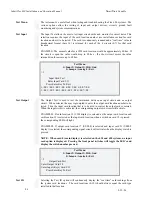
The Output Test is used to test the interaction between an input circuit and an output
circuit. When selected the user is prompted to enter the output card location number to be
tested. Then the input card location that is to be used to control the output card is entered.
When the input circuit is activated, the corresponding output card circuit will activate.
EXAMPLE1: If card location 12 (CIM display) is selected as the output card location and
card location 12 is selected as the input card location, when a switch on card 12 is pressed
the corresponding LED will light.
EXAMPLE2: If output card location 17 (USM-8) is selected and input card 21 (USM-8
display) is selected, the corresponding signal circuit will activate when the display switch is
pressed.
NOTE : When card 0 (main display) is selected on the 630 and 650 systems, no input
card option is displayed. Pressing the front panel switches will toggle the LED’s and
display the switch number pressed.
Test Menu
1=Input 2=Output 3=ID 4=Gnd
5=Lamp 6=Analog 0=Exit
>2
Output Card Test
Enter Output Card #:9
Enter Input (Keys) Card #:13
Press Enter Key To Exit
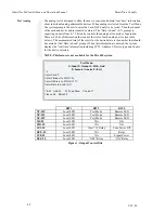
Test ID
Selecting the Test ID option will continuously display the “real time” card readings from
the system card locations. The card locations (0-39) should always equal the card type
installed in that location.
Summary of Contents for Smart Start IDENTIFLEX 630
Page 2: ......
Page 4: ......
Page 6: ......
Page 11: ...Section 1 IDENTIFLEX 630 System Description...
Page 14: ......
Page 44: ......
Page 117: ...Section 1 IF 600 FIRMWARE VERSION R7 MANUAL SUPPLEMENT Introduction...
Page 123: ...Section 2 IF 600 FIRMWARE VERSION R7 MANUAL SUPPLEMENT Special System Functions...
Page 127: ...Section 3 IF 600 FIRMWARE VERSION R7 MANUAL SUPPLEMENT System Test Mode...
Page 141: ...Section 4 IF 600 FIRMWARE VERSION R7 MANUAL SUPPLEMENT Programming...
Page 201: ...Section 4 IF 600 FIRMWARE VERSION R7 MANUAL SUPPLEMENT Configuration File...


