background image

6

Floor Stand Assembly

The stringing machine uses a four leg floor 

stand design. The legs must be assembled 

to the lower column before use. Remove 

all parts from the shipping carton to con-

firm that contents match the list of parts on 

Page 5.

ASSEMBLY  INSTRUCTIONS

Floor Stand Leg Assembly

Align the holes in the leg flange with 

the matching holes in the lower column. 

Secure the leg with one M8 FLAT HEAD 

screw through the upper hole, and one M8 

SOCKET HEAD cap screw through the 

bottom hole. Install one 8mm nut on each 

screw.  Repeat this procedure for the three 

remaining legs.

Floor Stand  Assembly (Continued.)

To complete the floor stand, screw the height adjust-

ment locking knob (“A”) into the side of the lower 

column. The locking knob should not protrude beyond 

the inside surface of the lower column at this time.

Summary of Contents for 6900 Els

Page 1: ...OWNER S MANUAL Issue 1 April 2010 6900 Els STRINGING MACHINE 6 POINT MOUNTING...

Page 2: ......

Page 3: ...ustment as described on page 20 and the cleaning procedures listed on page 21 GAMMA s obligation under this warranty is limited to repair or replacement of defective EQUIPMENT and no one is authorized...

Page 4: ...t Mounting System Accommodates All Racquets Parallel Jaw Rotating Gripper w Diamond Dust Coated Grip ping Surfaces Professional Quick Action Dual Action Rotating Metal Fixed String Clamps w Diamond Du...

Page 5: ...ce the cartons are opened remove all inner cartons and check to be sure that all parts are present and accounted for Contents of Floor Stand Carton 1 Lower Column 1 Upper Column with Flange Plate 4 Le...

Page 6: ...in the leg flange with the matching holes in the lower column Secure the leg with one M8 FLAT HEAD screw through the upper hole and one M8 SOCKET HEAD cap screw through the bottom hole Install one 8mm...

Page 7: ...ition and place it in the appropriate hole to set the desired height of the machine Be sure to thread the screw completely into the upper column so the head of the cap screw rests in the notch of the...

Page 8: ...operation Turntable and Mounting System Installation To install the turntable remove the four nuts holding the mounting bolts in place during shipment Position the turntable over the turntable pin an...

Page 9: ...ded knob to the end of the rod The string reel holder can hold up to 5 reels of string depending on the size of the string reel Before placing the first reel on the rod slide two M8 washers over the p...

Page 10: ...ower cord into the AC Adapter and then insert the female end of the cord from the AC Adapter into the A C Power Cord Socket C located on the back panel of the tensioner Plug the male end of the power...

Page 11: ...measurement Knot Function Increases pulling tension by 10 over the setting value max 90 lbs 40 8 kgs for one pull During the pull the LED stays lit to indicate the Knot function is enabled Tension Ind...

Page 12: ...be adjusted to provide maximumsupporttotheracquetframe Rotate the support so that the pads contact the frame squarely when the arms are closed against the racquet Should the shoulder supports block s...

Page 13: ...cure the string The clampingpressureappliedtothestringshould be adjusted to provide sufficient pressure to secure the string when subjected to the desired pulling tension The diamond coated gripper pl...

Page 14: ...o apply tension wrap the string clockwise around the gripper drum and position the string between the gripper jaws The string must pass over the upper gripper jaw before being placed between the gripp...

Page 15: ...er and under the main strings being careful to alternate the weave direction of each consecutive cross string so as to be opposite of the previously installed cross string To apply tension to a string...

Page 16: ...ned and clamped tieoffattheappropriateholespeci fiedbytheracquetmanufacturer Removethe framefromthemountingsystembyloosening the shoulder supports and frame supports STRINGING THE FRAME BadmintonShoul...

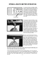
Page 17: ...of pressure to the string and wipe down the surface of the string to prevent debris from entering the SLM When the end of the string exits through the hole on the right press the C or Enter Clear but...

Page 18: ...ldingthestring slowlypullthesheath out of the grommet hole to leave the free end of the string exposed The machine includes the pathfinder string ing awl which creates a pathway between or around stri...

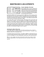
Page 19: ...the calibrator does not match the tension displayed on the machine use the tension indexing buttons to match the display to the calibrator reading and press the Enter Clear button 4 Release the tensio...

Page 20: ...e the clamp base and clamp stop in reverse order Adjusting the String Clamp Jaw Spacing The string clamps will need minor adjust ments according to what string type con struction and gauge you are usi...

Page 21: ...rasive tool such as a toothbrush also works well to remove oily or greasy build up PROBLEM SOLUTION String slips in clamps Adjust gap between clamp jaws Clean clamp jaws String slips in gripper Clean...

Page 22: ...AD 346 LOWER COLUMN SUPP 347 UPPER COLUMN SUPP 348 ALUMINUM FRAME 349 TENSIONER E77 KEY PAD ELECTRONICS E82 SLM RECEPTACLE MMSC UNIVERSAL STRING CLAMP MRSGD DIE CAST GRIPPER MQAC SHORT QA BASE CLAMP 1...

Page 23: ...23 PARTS DRAWING SB SQ T B MFSPP 339 E77 MRSGD 210 212 211 106 344 343 342 349 121 347 346 114 283 285 286 308 320 289 329 115 348 6B 327 MBMSP MMSPP 6B 304 337 299 341 340 345 E82 MQAC MMSC...

Page 24: ...GAMMA SPORTS 200 Waterfront Drive Pittsburgh Pennsylvania 15222 Phone 800 333 0337 Fax 412 323 0317 Visit our website at www gammasports com Copyright 2010 GAMMA Sports All Rights Reserved...

Reviews: