background image

10

STRINGING THE FRAME

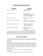
String Gripper Operation

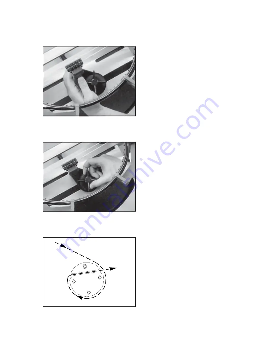
To insert the string in the split drum string
gripper, wrap the free end of the string
clockwise around the gripper drum and po-
sition the string between the gripper jaws as
shown in the illustration.

The string must pass over the top half of the
gripper before being placed between the
diamond coated plates of the upper and

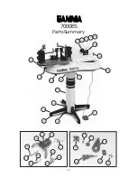
lower gripper jaws. Excessive slack in the
string should be removed before applying
tension. As the drum turns and applies ten-
sion to the string, the upper jaw is forced
down to clamp the string between the jaws.

Fixed Clamp Operation

The fixed clamps supplied with your GAMMA
7000Es are of a dual action design. The
string clamp and the clamp base operate
independently of one another.

To clamp a string, lift the clamp head and
place the string between the jaws. Depress
the clamp head lever to secure the string.
The clamping pressure applied to the string
should be adjusted to provide sufficient pres-
sure to secure the string when subjected to
the desired pulling tension. The diamond
coated gripper plates provide for increased

friction between the clamps and the string to allow for reduced clamping pressure while securing
and holding the string under tension.

Fixed Clamp Operation

Rotate the winged lock knob clockwise to
secure the clamp base to the turntable.

Reverse the clamping procedure to unlock
the string clamp.

The winged lock knob should be tightened
enough to prevent clamp base slippage on
the turntable, when the desired tension is
placed on the string. To go from the loose
position to the clamped position and back,
generally requires about 1/2 to 3/4 quarters
of a turn. Although when stringing at ex-
tremely high tensions, additional tightness

may be required. 

Note: If the string slips in the string clamp while tensioning, adjust the

gap between the clamp jaws as per the instructions on page 14.

Summary of Contents for 7000 Es

Page 1: ...OWNER SMANUAL Issue3 March29 1999 Issue3 March29 1999 Issue3 March29 1999 Issue3 March29 1999 Issue3 March29 1999 7000 Es STRINGINGMACHINE Copyright1999GAMMASports AllRightsReserved...

Page 2: ...part wear and tear as a result of normal use GAMMA s obligation under this warranty is limited to repair or replacement of defective EQUIPMENT and no one is authorized to promise any other liability G...

Page 3: ...w for aramid and metallic fast for synthetic and gut 5 6 Point Suspension Mounting System 10 point support 6 Dual Action Swivel Composite Coated Steel String Clamps w Diamond Coating 7 Convenient Foot...

Page 4: ...AIN IN PLACE TO PROTECT THE TENSIONER WHILE REMOVING IT FROM THE INNER CARTON Small Post Carton Contains 1 Lower Post 2 Upper Post with Flange 4 Legs 1 Winged Locking Knob Screw 4 M8 x 25 Flat Head Sc...

Page 5: ...Cont Align the holes in the leg flange with the matching holes in the lower column support post Secure the leg with one FLAT HEAD cap screw through the upper hole and one SOCKET HEAD cap screw through...

Page 6: ...ing the four corner feet remove the four 4 button head cap screws and flat washers from the base of the tensioner ASSEMBLYINSTRUCTIONS Unpacking the Tensioner The tensioner assembly is packed and se c...

Page 7: ...four cap screws and flat washers Height Adjustment The turntable height of the Gamma 7000ES is adjustable from 39 to 46 To change the height remove the socket head cap screw from its current position...

Page 8: ...de bushing Be careful not to lose the radial thrust bearing components located in the center recess of the knob Align the clamp base with the clamp slot of the turntable base Insert the clamp guide bu...

Page 9: ...g to the power supply check the voltage supply switch setting located on the side panel as shown in Figure 2 To change from 110 volts service to 220 volt service simply slide the switch fully to the r...

Page 10: ...support post assemblies clockwise Adjust the supports until firm contact is made between the shoul der supports and the frame The tear drop shaped holes torwards the back of the shoulder supports are...

Page 11: ...ion rotate the adjustment knob clockwise to decrease the displayed ten sion counter clockwise to increase the dis played tension until the desired tension is displayed on the digital display Setting T...

Page 12: ...ress the clamp head lever to secure the string The clamping pressure applied to the string should be adjusted to provide sufficient pres sure to secure the string when subjected to the desired pulling...

Page 13: ...nd the the green LED turn on As the tensioned string stretches the gripper will rotate intermit tently to maintain the set tension To release the string after clamping press the tension switch and the...

Page 14: ...ing is tensioned and clamped tie off at the appropriate hole speci fied by the racquet manufacturer Remove the strung racquet by loosening the shouldersupportsandsupportslidesinsmall increments until...

Page 15: ...ole in the same manner as for traditional awls The Pathfinder awl must be in the closed position before insertion Once the awl is inserted pull the handle of the awl outward while holding the tip sect...

Page 16: ...the range can vary from 2 4 lbs depending on the string used to calibrate the machine and the speed of the tensioner For consistency we recommend that the tension setting of the machine be calibrated...

Page 17: ...ion calibrator and adjust machine calibration if necessary With time and use the clamping surfaces of your machine may become oily or dirty and result in string or clamp slippage while stringing Perio...

Page 18: ...16 7000ES Parts Summary 114 115 6B 121 129 131 32A 124 125 130 118A 128 126 36 33A 37 123 106 127 21B 21A 122A 135 13 136 22A 134 132 133 22A 54A 57A 57 58 52B 55 56...

Page 19: ...Bushing Nut 57 Load Bushing 57A Radial Thrust Bearing 58 Winged Knob 106 Wing Locking Knob Screw 114 Short Leg 115 Flat Head Cap Screw M8 x 25 118A Turntable SM 121 Leveling Foot 123 Gripper Drum Bac...

Reviews: