6
Section 2. Operation
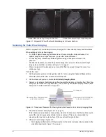
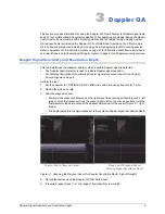
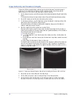
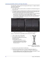
Figure 2-1. Doppler 403 Flow Phantom B-Mode Images of Vessel Sections
Scanning for Color Flow Imaging
Refer to
Appendix A: Flow Velocity Accuracy
on page 27 for flow velocity theory and calculations.
When setting up for color flow imaging:
•
A 5 MHz or higher frequency transducer is best for scanning the horizontal vessel. For
optimal images, use a higher frequency to view the horizontal vessel.
•
A lower frequency transducer provides optimal viewing of deeper structures in the
phantom.
•
Position the transducer such that the phantom targets are viewed in the same left-to-right
image plane orientation as shown in Figure 1-2 on page 2.
•
When viewing color flow images, keep in mind that fluid is pumped through the vessel in a
continuous loop.
Perform the scan:
1
On the phantom, select a mid-range flow rate (5–7 ml/s) using the
Fast
and
Slow
buttons.
Wait a few seconds for flow to reach the selected rate.
2
On the ultrasound system, activate
Color Velocity Imaging Mode
.
3
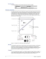
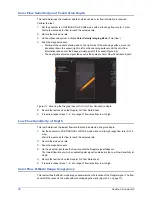
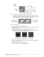
Select a color scheme that distinguishes flow towards the transducer (“positive flow”) from flow
away from the transducer (“negative flow”). The commonly used BART display scheme (Blue
Away, Red Towards) is shown in Figure 2-2.
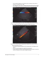
Figure 2-2. Transducer Placement for Viewing Horizontal Vessel in Color Velocity Imaging Mode
4
Scan the horizontal vessel (Figure 2-3 on page 7).
If the transducer is a phased or convex array, place the transducer so that the central acoustic
axis of the color image is perpendicular to the vessel axis. This can be determined by
visualizing the inner and outer surface of the vessel wall, top and bottom.
5
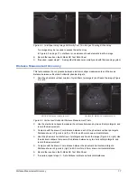
Observe the following in Figure 2-3:
• Color display verifies right-to-left flow direction for the horizontal vessel when scanned in the
orientation depicted in Figure 1-2 on page 2.
Image plane projecting through horizontal
Image plane projecting through diagonal
Flow toward the transducer
color scheme (red)
Flow away from the transducer
color scheme (blue)
Transducer

