Distance Measurement Accuracy
17
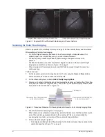
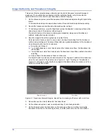
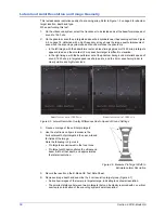
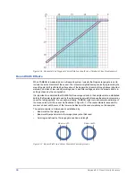
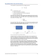
Figure 4-3. Curvilinear Array Image Uniformity Test, Two Images Covering Entire Array
Two images may be required to assess the entire array.
In Figure 4-3 on page 17, note there is no evidence of dead elements in either image.
8
Record the results on the B-Mode QC Test Data Sheet.
9
If required, repeat steps
-
using other transducers normally used with this scanning system.
Distance Measurement Accuracy
This test assesses the congruence between electronic caliper measurements and the known
distance between vertical and horizontal phantom targets.
1
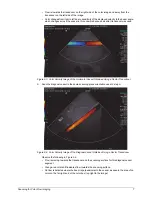
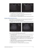
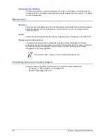
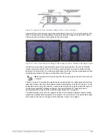
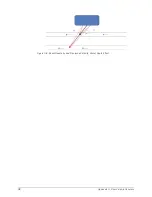
Scan the phantom’s vertical column of nylon fibers (‘pin targets’) and freeze the image (Figure
4-4, left).
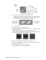
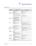
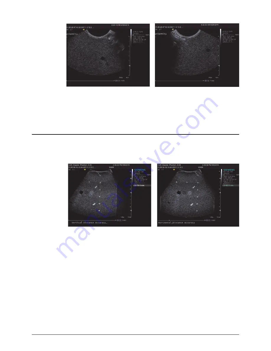
Figure 4-4. Vertical and Horizontal Distance Measurement Tests
2
Use the electronic calipers to measure the distance between any two vertical pin targets, and
record the measurement.
3
Compare with the known 2 cm distance between each of the phantom’s vertical pin targets.
Distance shown in Figure 4-4 (left) is 79.4 for an 80 mm known vertical distance.
4
Scan the phantom’s horizontal row of pin targets and freeze the image (Figure 4-4, right). Use
the electronic calipers to measure the distance between any two horizontal pin targets, and
record the measurement.
5
Compare with the known 3 cm distance between the phantom’s horizontal pin targets.
Distance shown in Figure 4-4 (right) is 60.5 mm for a 60 mm known horizontal distance.
6
Record the results on the B-Mode QC Test Data Sheet.
7
If required, repeat steps
at additional vertical and horizontal distances.
Vertical distance measurement
Horizontal distance measurement

