18
Section 4. 2D B-Mode QA
Lateral and Axial Resolution and Image Geometry
This test assesses resolution quality of a scanning array. Refer to Figure 1-2 on page 2 for phantom
target location, depth and type.
When performing this test:
1
On the ultrasound system, select the transducer to be tested and set the beamformer speed of
sound to 1540 m/s.
2
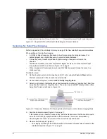
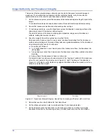
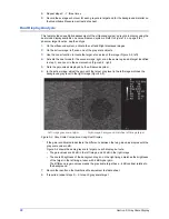
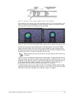
On the phantom, scan the pin targets and anechoic cylinders near the scanning surface. Figure
4-5 on page 18, obtained with a high frequency array, shows the image quality improvement
seen when the scanning system speed of sound matches the phantom’s.
• In the left image, with the beamformer set at a breast imaging preset of 1490 m/s, pin targets
appear broad, and the smallest (2 mm) anechoic target is difficult to visualize.
• In the right image, with the beamformer set at the phantom background material’s speed of
sound, 1540 m/s, pin targets appear as sharp points, and the 2 mm anechoic cylinder is
clearly visible and highly resolved.
Figure 4-5. Lateral Resolution Quality Differences Due to Speed of Sound Settings
3
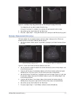
Freeze an image of the vertical pin targets.
4
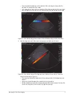
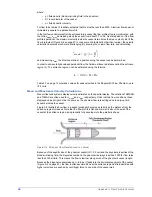
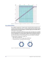
Use the electronic calipers to measure the
horizontal width of pin targets in the near, mid and
far fields of the image.
Note the following in Figure 4-6:
• Pin targets are narrowest in the focal zone.
• Pin target width demonstrates the ultrasound
beam width at that depth, and approximates
the lateral resolution.
Figure 4-6. Measure Pin Target Width to
Estimate Lateral Resolution
5
Record the results on the B-Mode QC Test Data Sheet.
6
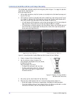
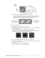
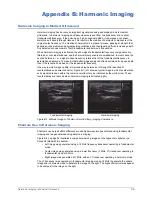
Decrease image depth and examine the 4 cm resolution target group (Figure 4-7).
• Notice how images of the lower pin targets merge, indicating lack of axial resolution.
• The smallest distance between two pin targets that can be clearly resolved with no vertical
overlap is an indication of the scanning system’s axial resolution.
Beamformer set at 1490 m/s
Beamformer set at 1540 m/s


