Lateral and Axial Resolution and Image Geometry
19
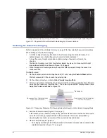
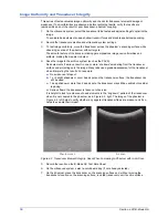
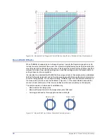
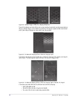
Figure 4-7. Resolution Target Group at 4 cm Indicates Axial Resolution
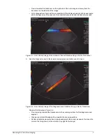
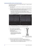
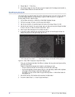
• Pin targets are resolved axially if an imaginary horizontal line can be drawn between the
imaged targets on the scan, without touching either target image (Figure 4-8 on page 19).
• Pin targets on the left are not resolved; targets on the right are resolved.
Figure 4-8. Axial Resolution
7
Record the results on the B-Mode QC Test Data Sheet.
8
Because axial resolution can change with depth, repeat steps
–
for other resolution target
groups at various depths.
9
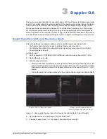
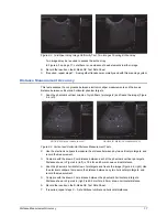
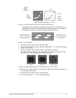
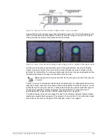
Scan the nearest cystic target group to assess image geometry (Figure 4-9).
Each target should be round with a clean black appearance and well defined edges. Bright
specular echoes at the top and bottom of the targets are normal.
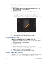
Figure 4-9. Checking Ultrasound System Geometry with 10 mm Cystic Target
10
Scan the 10 mm cystic target and use the electronic calipers to measure the dimensions from
top to bottom and side to side.
11
Record the results on the B-Mode QC Test Data Sheet.
12
If required, repeat steps
with a different transducer.
Horizontal line can
be drawn between
targets; indicates axial
resolution
Horizontal line cannot
be drawn between
targets; indicates lack
of axial resolution
Normal
Distorted
System noise

