Flow Profiles in the Doppler 403 Flow Phantom
29
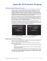
Figure A-4. Asymmetric Flow at Entrance Region After a Turn in the Vessel
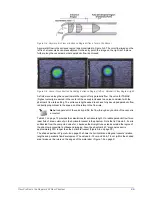
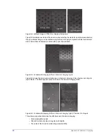
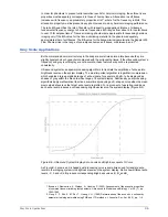
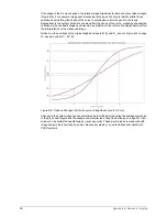
Asymmetric flow in the entrance region is demonstrated in Figure A-5. The color flow image on the
left is of a transverse scan plane adjacent to the entry point; the image on the right is of a plane
further along the vessel axis, where parabolic flow is achieved.
Figure A-5. Vessel Cross Section Illustrating Entrance Region (left) vs. Parabolic Flow Region (right)
As fluid moves along the vessel toward the region of fully parabolic flow, the value for TAMAX
(highest velocity, measured in the center of the vessel) increases to a value consistent with the
phantom’s flow rate setting. The entrance length needed to achieve fully developed parabolic flow
is directly proportional to the speed, and therefore to the flow rate.
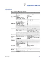
Table 3-1 on page 13 provides the calculations for entrance length
L
to realize parabolic flow for an
ideal fluid of known viscosity in the horizontal vessel in the phantom. Note that in Column 3, 5 cm is
subtracted from the computed value for
L
because the straight tube extends outside the region of
the phantom accessible to ultrasound imaging. Also, the phantom’s 40° diagonal vessel is
approximately 30% longer than the horizontal vessel (Figure A-6 on page 30).
The shaded portion in Figure A-6 on page 30 shows the horizontal and diagonal vessels' relative
lengths and parabolic flow development. The values: 6–19 cm and 24.8–7.8 cm (within the shaded
area) make up the rulers on the edges of the water dam (Figure 1-2 on page 2).
Note:
Independent of the velocity profile, the flow through any section of the vessel is
a constant.

