Beam Width Effects: Spectral Broadening
31
Beam Width Effects: Spectral Broadening
For flow parallel to the ultrasound beam axis, the Doppler equation is
where
• f
d
= Doppler frequency shift
• f
t
= frequency transmitted by the transducer
•
v
= velocity of scattering particles in the blood-mimicking fluid
•
c
= speed of sound in the medium
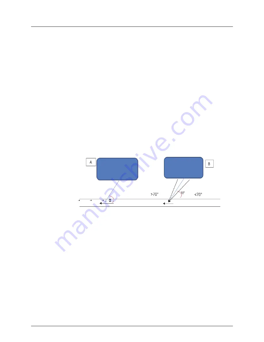
If the direction of the incident beam makes an angle (
α
) with the direction of flow in the vessel as
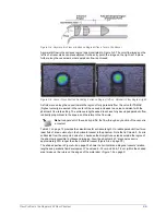
shown in Figure A-8A, the velocity
v
in the Doppler equation must be replaced with the component
of the velocity in the direction of the incident beam, which is
vcos(
α
)
. Solving the Doppler equation
for the velocity of the scatterers, we get
Knowing the Doppler shift and beam angle relative to the direction of flow it is possible to estimate
the scatterers' velocity. Spectral analysis software in the instrument yields the Doppler frequency
shift, and the spectral scale is calibrated to display the velocity.
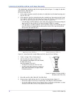
Figure A-8. Beam Geometry and Displayed Velocity
An important influence on estimated velocity is the Doppler angle, which is established by the
direction of the beam and the direction of reflectors over the beam. In most situations an
angle
correct
cursor is adjusted so that it is parallel to the vessel walls, and hence to the assumed direction
of flow. The instrument reads the angle between the cursor and the beam axis, then corrects the
spectral velocity scale according to the cosine of this angle.
However, since the ultrasound beam usually is focused into the sample volume from a finite
aperture, the Doppler angle is not the single value beam axis typically displayed, but includes a
range of angles. For example, contributions to the Doppler signal from the right side of the beam
(shown schematically in Figure A-8B) result in slightly higher Doppler frequency shifts than
contributions from along the beam axis where the angle correct operation applies. Therefore,
depending on the actual beam geometry, there may be a greater displayed velocity than expected
based on the known flow conditions. As Figure A-9 on page 32 shows, any errors of this type are
dependent on vessel depth.
f
d
2f
t
v
c
--
=
v
2f
d
c
2f
t
----------------
cos
=


