Flow Velocity Profiles
13
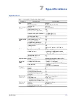
Table 3-1, column 5, Entry Length (cm), provides the calculated entrance lengths required to
achieve parabolic flow at 22 °C for the blood-mimicking fluid inside the vessel, which has a density
of 1.03 g/cc, a viscosity of 4.1 cP, and an inside diameter of 0.5 cm. As shown in the table, for a flow
rate of 6 ml/s, parabolic flow conditions are achieved after about 10.54 cm. This location can be
found by referring to the rulers on the water dam.
At locations short of the entrance length required for parabolic flow, the maximum velocity along the
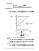
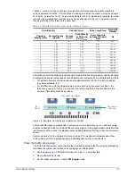
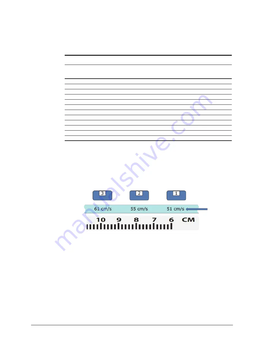
vessel axis has a value that depends on the Doppler measurement point. As illustrated in Figure 3-6:
•
For a volume flow rate of 6.0 ml/s and vessel inside diameter of 0.5 cm, 10.54 cm is needed
to achieve parabolic flow.
•
For this flow rate, with the Doppler sample volume defined by transducer position 3, the
ratio v
max
/v
mean
is 61.1/30.6 = 2. However, the ratio is less than 2 at points closer to the
entrance (right side of scanning surface).
Figure 3-6. Example, Flow Velocity and Parabolic Profiles
In the horizontal vessel, parabolic flow is achieved at volume flow rates up to 11 ml/s for sample
volumes positioned on the far left side of the scanning surface. In the diagonal vessel, parabolic flow
is achieved at all flow rates. The diagonal vessel is approximately 30% longer than the horizontal
vessel.
Refer to
Appendix A: Flow Velocity Accuracy
on page 27 for additional information about flow
velocity theory and the calculations used in estimating flow velocity in the phantom.
Flow Velocity Accuracy
The Flow Velocity Accuracy test evaluates the congruence between the flow velocity displayed on
the ultrasound system and the flow velocity displayed on the phantom.
1
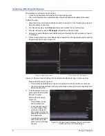
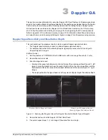
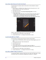
Set the phantom to CONTINUOUS mode with a low (1–2 ml/s) flow rate.
2
Record the mode and rate.
3
On the ultrasound system, activate
PW Doppler
mode.
Table 3-1. Flow Rate Estimated Velocities for Horizontal Vessel
Flow Rate (Q)
Velocity (cm/s)
Entry Length (cm) Reynolds
Number
Phantom
Display (ml/s)
System Display
(ml/min)
Average
(v
mean
)
Peak Velocity
at Parabolic
Flow (v
max
)
Entry Length to
Achieve Parabolic
Flow
Re
1
60
5.1
10.2
1.76
58.57
2
120
10.2
20.4
3.51
117.14
3
180
15.3
30.6
5.27
175.71
4
240
20.4
40.7
7.03
234.28
5
300
25.5
50.9
8.79
292.85
6
360
30.6
61.1
10.54
351.41
7
420
35.7
71.3
12.30
409.98
8
480
40.7
81.5
14.06
468.55
9
540
45.8
91.7
15.81
527.12
10
600
50.9
101.9
17.57
585.69
11
660
56.0
112.0
19.33
644.26
12
720
61.1
122.2
21.08
702.83
Flow rate =
6.0 ml/s
Transducer positions
ID =
0.5 cm

