18
Flow Sensitivity at Depth
This test determines the lowest flow rate that can be detected at a given depth.
1.
Set the 1425A Doppler Phantom to produce a pulsatile or constant flow in the mid to high-
range of flow rates.
2.
Scan the angled vessel at a depth of 5 cm.
3.
Decrease the flow rate until the Doppler display disappears. The lowest flow rate at which a
useful Doppler signal is obtained is the flow sensitivity.
4.
Repeat this test at various depths in the phantom.
5.
Record the results on the Doppler QC Test Data Sheet.
Color Flow B-Mode Image Congruency
Verify that the B-mode image vessel is where the Doppler signal is. The flow should fill the vessel
to the walls and should not overlap the walls.
1.
Set the 1425A Doppler Phantom to constant flow mode.
2.
Set the scanner’s color flow output power and color gain for maximum sensitivity without
excessive noise.
3.
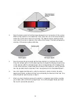
Toggle between color flow and B-mode. Observe whether the color flow information is dis-
played only in the vessels. Record scanner settings that produce poor congruency. Also note
whether the highest flow occurs at the vessel’s center and the lowest flow at the vessel wall.
4.
Record the results on the Doppler QC Test Data Sheet.
Directional Discrimination
Flow moves either toward or away from the transducer. The Directional Discrimination test evalu-
ates the scanner’s ability to accurately display flow direction.
With the flow perpendicular to the Doppler beam, Doppler signals resulting from spectral broad-
ening are usually obtained. If the beam is perpendicular to flow, the spectral broadening artifact
should be equally positive and negative and the magnitude of the signals should be the same.
Summary of Contents for Optimizer
Page 26: ...26 Notes...
Page 27: ...27 Notes...


