Chapter 5: Calibration
5-3
3)
Verify that all settings for the electronic load or programmable power supply in the LPI Configuration
Entry setup window are correct.
4)
Open Gamry Framework™ software and open the LPI calibration experiment using one of the methods
discussed in the previous section
5)
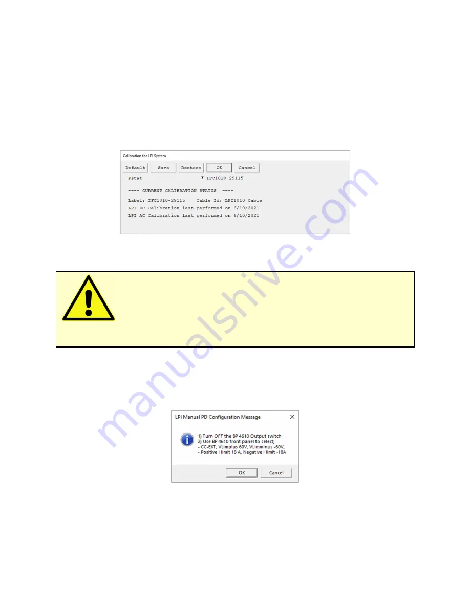
The
LPI Calibration
window appears, see Figure 5-4. Click the
OK
button and exactly follow each setup
instruction before continuing with the next step
Figure 5-4
LPI Calibration setup window
The setup window shows the potentiostat used for calibration. Select the correct device for the LPI
calibration. Further below in the setup window are the previous LPI calibration results listed included the
date. If a calibration was not successful, an error message is shown instead.
6)
A safety message appears followed by an instruction to configure your electronic load or programmable
power supply settings, see Figure 5-5. These settings can vary depending on the instrument you are using.
Press
OK
after setting all parameters.
Figure 5-5
LPI Manual PD Configuration window
7)
An instruction window appears to install your first calibration cell, see Figure 5-6. Note that LPI calibration
requires at least two different calibration cells with different resistors. In this case, the 2 Ω cell is the first.
Caution:
The LPI calibration is a semi-automatic procedure which requires the user to
change the calibration cell at least once during the process. The electronic load or programmable power supply
needs to be operated individually, requiring user interaction.
Summary of Contents for LPI1010
Page 2: ...ii...
Page 6: ......
Page 14: ......
Page 30: ...Chapter 4 Hardware Installation 4 10...
Page 36: ......
Page 62: ......
Page 64: ......
Page 66: ......
Page 67: ...Appendix D Certificate of conformity Appendix D VII Certificate of conformity...
Page 68: ...Appendix D Certificate of conformity Appendix D VIII...


