background image

Der IP-Matrixswitch »ControlCenter-IP-XS«

G&D ControlCenter-IP-XS · 

5

Deutsch

Der IP-Matrixswitch 

»ControlCenter-IP-XS«

Der IP-Matrixswitch 

ControlCenter-IP-XS

 ist die zentrale Komponente des G&D IP-

Matrixsystems.

Das IP-Matrixsystem ermöglicht die Aufschaltung eines IP-Arbeitsplatzmoduls (

CON

auf ein IP-Rechnermodul (

CPU

). Durch die Aufschaltung wird das Videobild des am


Rechnermodul angeschlossenen Computers auf dem Arbeitsplatz-Monitor angezeigt. 

Mit der Tastatur und Maus des Arbeitsplatzes bedienen Sie den aufgeschalteten Com-

puter.

Sie können beliebige Geräte der 

Vision-IP

- und der 

VisionXS-IP

-Serie als Endgeräte der 

IP-Matrix einsetzen.

Lieferumfang

1 × IP-Matrixswitch 

ControlCenter-IP-XS

1 × Servicekabel (

Micro-USB-Service-2

)

1 × EasyStart-Flyer

1 × Sicherheitshinweise-Flyer

HINWEIS: 

Der IP-Matrixswitch unterstützt maximal 20 Endgeräte.

ControlCenter-IP-XS

Summary of Contents for ControlCenter-IP-XS

Page 1: ...A9100391 1 00 G D ControlCenter IP XS DE Installationsanleitung EN Installation Guide ...

Page 2: ... Gewährleistung für Geräte die nicht bestimmungsgemäß eingesetzt wurden nicht autorisiert repariert oder modifiziert wurden schwere äußere Beschädigungen aufweisen welche nicht bei Lieferungserhalt angezeigt wurden durch Fremdzubehör beschädigt wurden G D haftet nicht für Folgeschäden jeglicher Art die möglicherweise durch den Einsatz der Produkte entstehen können Warenzeichennachweis Alle Produkt...

Page 3: ...utzt Hochfrequenzenergie und kann diese ausstrahlen Wenn es nicht gemäß der Anleitung installiert wird kann es Funkstörungen ver ursachen Es wird jedoch keinerlei Garantie dafür übernommen dass die Störun gen bei einer bestimmten Installation nicht auftreten Wenn dieses Gerät Störungen beim Rundfunk oder Fernsehempfang verursacht was durch Aus und Einschalten des Geräts ermittelt werden kann beheb...

Page 4: ...st Übertragung 8 Installation 9 Stromversorgung 9 Netzwerkschnittstelle 9 Installation und Anschluss der Arbeitsplatzmodule 10 Installation und Anschluss der Rechnermodule 11 Erstkonfiguration der Netzwerkeinstellungen 12 Reset der Netzfilterregeln 14 Grundkonfiguration der KVM over IP Verbindung 15 Aufnahme von Endgeräten 15 Endgeräte entkoppeln 16 Festlegung der Art der Videoübertragung 17 Besch...

Page 5: ...device has been disconnected from all power sources Disconnect all power plugs and all power supplies of the device Débranchez toutes les sources d alimentation Avant l installation assurez vous que l appareil a été débranché de toutes les sources d alimentation Débranchez toutes les fiches d alimentation et toutes les alimentati ons électrique de l appareil Vorsicht vor Stromschlägen Um das Risik...

Page 6: ... bei der Verlegung der Kabel Stolperfallen Geerdete Spannungsquelle verwenden Betreiben Sie dieses Gerät nur an einer geerdeten Spannungsquelle Verwenden Sie ausschließlich das G D Netzteil Betreiben Sie dieses Gerät nur mit dem mitgelieferten oder in der Bedienungsanlei tung aufgeführten Netzteil Betreiben Sie das Gerät ausschließlich im vorgesehenen Einsatzbereich Die Geräte sind für eine Verwen...

Page 7: ...ebrauchte Batterien dürfen nicht in den Hausmüll geworfen werden Beachten Sie die gültigen Vorschriften zur Entsorgung elektronischer Produkte CAUTION Risk of explosion if the battery is replaced by an incorrect battery type Dispose of used batteries in an environmentally friendly manner Do not dispose of batteries in municipal waste Check local regulations for the disposal of electronic products ...

Page 8: ...e verwenden Es ist nicht zulässig Lichtwellen Module zu verwenden die nicht der Laser Klasse 1 gemäß EN 60825 1 2014 entsprechen Durch die Verwendung solcher Module kann die Einhaltung von Vorschriften und Empfehlungen zum sicheren Umgang mit Laser Technologie nicht sichergestellt werden Die Gewährleistung zur Erfüllung aller einschlägigen Bestimmungen kann nur in der Gesamtheit der Originalkompon...

Page 9: ...e Aufschaltung wird das Videobild des am Rechnermodul angeschlossenen Computers auf dem Arbeitsplatz Monitor angezeigt Mit der Tastatur und Maus des Arbeitsplatzes bedienen Sie den aufgeschalteten Com puter Sie können beliebige Geräte der Vision IP und der VisionXS IP Serie als Endgeräte der IP Matrix einsetzen Lieferumfang 1 IP Matrixswitch ControlCenter IP XS 1 Servicekabel Micro USB Service 2 1...

Page 10: ... kehrs durch einen Netzwerk Switch bezeichnet Durch das Abhören der IGMP Konversation können die Switches feststellen welche ihrer eigenen Hosts einen Multicast Stream angefordert haben Nur diese Hosts werden mit dem geforder ten Multicast Stream versorgt IGMP Snooping Querier Ein IGMP Snooping Querier Funktion des Switches fragt in regelmäßigen Abständen alle Abonnenten einer Multicast Gruppe ob ...

Page 11: ...ner Multicast Gruppe auf eine andere geschaltet wird weil kurzzeitig beide Multicast Streams an den Port gesendet werden Deaktivierung des Spanning Tree TCN Flooding Wenn mehrere Netzwerk Switches im Einsatz sind wird Spanning Tree verwendet um sicherzustellen Vermeidung von Loops dass immer nur ein Datenpfad existiert Wird ein neuer Datenpfad erkannt aktiviert der Switch kurzzeitig das TCN floo d...

Page 12: ...senden die Target Module IP CPU die Videostreams per Unicast an die Arbeitsplatzmodule IP CON Die Aufschaltung eines Benutzers auf einen Computer auf den bereits ein anderer Benutzer aufgeschaltet ist ist in diesem Modus nicht möglich Meldung No multicast video HINWEIS Bei Verzicht auf die Multicast Übertragung werden deutlich weniger Anforderungen an den Netzwerkswitch gestellt Folgende der oben ...

Page 13: ...telle Network Stecken Sie ein als Zubehör erhältliches Twisted Pair Kabel der Kategorie 5e oder höher ein Das andere Ende des Kabels ist mit dem Gigabit Ethernet zu ver binden HINWEIS Stellen Sie bei der Standortwahl des Gerätes sicher dass die zulässige Umgebungstemperatur siehe Technical data auf Seite 22 in der unmittelbaren Nähe eingehalten und nicht durch andere Geräte beeinflusst wird Servic...

Page 14: ...lgende Sicherheitshinweise Blickkontakt mit dem unsichtbaren Laserstrahl vermeiden auf Seite 4 Optische Anschlüsse stets verbinden oder mit Schutzkappen abdecken auf Seite 4 Ausschließlich von G D zertifizierte Übertragungsmodule verwenden auf Seite 4 Handbuch Artikelnummer Download Link DL DVI Vision IP A9100327 https gdsys de A9100327 DL DVI Vision IP Fiber A9100328 https gdsys de A9100328 DP1 2...

Page 15: ...1040 10 und 1040 11 Beachten Sie diesbezüglich folgende Sicherheitshinweise Blickkontakt mit dem unsichtbaren Laserstrahl vermeiden auf Seite 4 Optische Anschlüsse stets verbinden oder mit Schutzkappen abdecken auf Seite 4 Ausschließlich von G D zertifizierte Übertragungsmodule verwenden auf Seite 4 Handbuch Artikelnummer Download Link DP1 2 Vision IP A9100311 https gdsys de A9100311 DP1 2 Vision ...

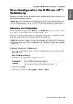
Page 16: ...t 3 Schalten Sie den IP Matrixswitch ein 4 Starten Sie den Webbrowser des Rechners und geben Sie in der Adresszeile die URL https 192 168 0 1 ein 5 Geben Sie in die Login Maske folgende Daten ein 6 Klicken Sie auf Login HINWEIS Im Auslieferungszustand sind folgende Einstellungen vorausgewählt IP Adresse der Netzwerkschnittstelle A 192 168 0 1 globale Netzwerkeinstellungen Bezug der Einstellungen v...

Page 17: ...as lokale Netzwerk Betriebsmodus Wählen Sie den Betriebsmodus der Schnittstelle A aus Aus Netzwerkschnittstelle ausschalten Statisch Es wird eine statische IP Adresse zugeteilt DHCP Bezug der IP Adresse von einem DHCP Server IP Adresse Geben Sie nur bei Auswahl des Betriebsmodus Statisch die IP Adresse der Schnittstelle an Netzmaske Geben Sie nur bei Auswahl des Betriebsmodus Statisch die Netzmask...

Page 18: ...ne Systemzugang deaktiviert und alle eingehenden Datenpa kete mit den Netzfilterregeln verglichen Mit dieser Funktion können die angelegten Netzfilterregeln vollständig gelöscht werden So löschen Sie die eingerichteten Netzfilterregeln 1 Starten Sie das On Screen Display mit dem Hotkey Strg Num Standard 2 Betätigen Sie die F11 Taste zum Aufruf des Konfiguration Menüs 3 Wählen Sie die Zeile System ...

Page 19: ...ofort betriebsbereit So nehmen Sie weitere Endgeräte auf 1 Starten Sie den Webbrowser des Rechners und geben Sie in der Adresszeile fol gende URL ein https IP Adresse des Gerätes 2 Geben Sie in die Login Maske folgende Daten ein 3 Klicken Sie auf Login 4 Klicken Sie im Menü auf Matrixsysteme Name Matrix HINWEIS In der Dokumentation der Webapplikation des IP Matrixswitches wer den alle Einstellunge...

Page 20: ...Gerätename IP Transmission IP Adresse der Transmission Schnittstelle IP Management IP Adresse der Management Schnittstelle MAC Transmission MAC Adresse der Transmission Schnittstelle MAC Management MAC Adresse der Management Schnittstelle UID physikalische ID des Geräts Status Anzeige ob das Gerät für die Aufnahme zu diesem Matrixswitch verfügbar ist oder bereits belegt ist TIPP Um alle zulässigen...

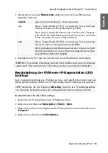
Page 21: ...st ist in diesem Modus nicht möglich Meldung No multicast video Sie können die Festlegung der Art der Videoübertragung systemweit festlegen Die systemweite Einstellung wird standardmäßig von allen Target Modulen angewen det Zusätzlich können Sie für jedes Target Modul die Art der Videoübertragung individuell festlegen So konfigurieren Sie die systemweite Einstellung der Multicast bzw Unicast Video...

Page 22: ...Die Target Module IP CPU versenden standardmäßig den Videostream per Multicast an die Arbeitsplatzmodule IP CON Diese Option Standard erlaubt Benutzern mit Multi Access Targetzugriff Recht die Aufschaltung auf einen Computer auf den bereits ein anderer Benutzer aufgeschaltet ist aus Die Target Module IP CPU versenden standardmäßig den Videostream per Unicast an die Arbeitsplatzmodule IP CON Die Au...

Page 23: ...e auf den Reiter KVM Verbindung System Systemweite Einstellung s oben anwenden an Dieses Target Modul IP CPU versendet den Videostream per Multicast an andere Arbeitsplatzmodule IP CON Diese Option erlaubt Benutzern mit Multi Access Targetzu griff Recht die Aufschaltung auf diesen Computer auch falls bereits ein anderer Benutzer aufgeschaltet ist aus Dieses Target Modul IP CPU versendet den Videos...

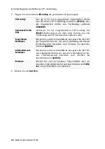
Page 24: ...der Zeile jedes Gerätes das eine Verbindung zum IP Matrixswitch aufbauen darf Target Modul hinzufügen Klicken Sie auf diese Schaltfläche und geben Sie die UID des Target Moduls ein das eine Verbindung mit diesem IP Matrixswitch herstellen darf Klicken Sie abschlie ßend auf Speichern Arbeitsplatzmodul hinzufügen Klicken Sie auf diese Schaltfläche und geben Sie die UID des Arbeitsplatzmoduls ein das...

Page 25: ...Die Verbindung mit dem Netzwerk wurde erfolgreich aufgebaut gelb an Es konnte keine Verbindung hergestellt werden Power grün an Der Matrixswitch wird mit Spannung versorgt und die Gerätesoftware wurde erfolgreich gestartet gelb an Der Matrixswitch wird mit Spannung versorgt blau an Die Identification Funktion wurde über die Webapplikation aktiviert aus Der Matrixswitch wird nicht mit Spannung vers...

Page 26: ...e Spannungsversorgung Anschluss 1 miniDIN 4 Power Buchse Spannung 12VDC Stromaufnahme 12 VDC 0 3 A Gehäuse Material Aluminium eloxiert Dimensionen B H T 109 mm 30 5 mm 184 mm Gewicht ca 0 6 kg Einsatzumgebung Temperatur 5 C bis 45 C Luftfeuchte 20 bis 80 nicht kondensierend Lagerumgebung Temperatur 20 C bis 55 C Luftfeuchte 15 bis 85 nicht kondensierend Konformität CE EAC RoHs ...

Page 27: ... Deutsch ...

Page 28: ...nty for devices that Are not used as intended Are repaired or modified by unauthorized personnel Show severe external damages that was not reported on the receipt of goods Have been damaged by non G D accessories G D will not be liable for any consequential damages that could occur from using the products Proof of trademark All product and company names mentioned in this manual and other documents...

Page 29: ...is equipment generates uses and can radiate radio frequency energy and if not installed and used in accordance with the instructions may cause harmful inter ference to radio communications However there is no guarantee that interfer ence will not occur in a particular installation If this equipment does cause harmful interference to radio or television reception which can be deter mined by turning...

Page 30: ...ission 8 Installation 9 Power supply 9 Network interfaces 9 Installing and connecting user modules 10 Installing and connecting computer modules 11 Initial configuration of the network settings 12 Resetting the netfilter rules 14 Basic configuration of the KVM over IP connection 15 Adding end devices 15 Unpair an end device 16 Determination of the type of video transmission 17 Restricting KVM over...

Page 31: ...llation assurez vous que l appareil a été débranché de toutes les sources d alimentation Débranchez toutes les fiches d alimentation et toutes les alimenta tions électrique de l appareil Trennen Sie alle Spannungsversorgungen Stellen Sie vor der Installation sicher dass das Gerät von allen Stromquellen getrennt ist Ziehen Sie alle Netzstecker und alle Spannungsversorgungen am Gerät ab Beware of el...

Page 32: ...oid tripping hazards while laying cables Only use a grounded voltage source Operate this device by using a grounded voltage source Use only the provided G D power pack Operate this device with the provided G D power pack or with the power pack listed in the manual Operate the device only in designated areas The devices are designed for indoor use Avoid exposure to extreme cold heat or humidity ...

Page 33: ... not dispose of batteries in municipal waste Check local regulations for the disposal of electronic products ATTENTION Il y a danger d explosion s il y a remplacement incorrect de la batterie Mettre au rebut les batteries usagées conformêment aux instructions du fabricant et de manière écologique Les batteries usagées ne doivent pas être jetées dans les ordures ménagères Respectez les prescription...

Page 34: ... not permitted to use fibre optic modules which do not meet the requirements of laser class 1 in accordance to EN 60825 1 2014 By using such modules the compli ance with regulations and advices for the safe handling of laser technology cannot be guaranteed The guarantee of complying with all relevant instructions can only be given by applying original components Therefore the devices have to be op...

Page 35: ...y accessing the computer connected to the computer module the video image is displayed at the console monitor You can now operate the accessed computer with console keyboard and console mouse You can use any device of the Vision IP and VisionXS IP series as end devices of the IP matrix Scope of delivery 1 IP matrix switch ControlCenter IP XS 1 service cable Micro USB Service 2 1 EasyStart flyer 1 ...

Page 36: ...ork switch By listening to the IGMP conversation the switches can deter mine which of their own hosts have requested a multicast stream Only these hosts are supplied with the required multicast stream IGMP Snooping Querier An IGMP snooping querier function of the switch regu larly asks all subscribers of a multicast group whether they still want to receive this group IGMP query The answers IGMP re...

Page 37: ...ences when switching from one multicast group to another because for a short time both multicast streams are sent to the port Deactivation of Spanning Tree TCN Flooding When multiple network switches are in use spanning tree is used to ensure loop avoidance that only one data path exists at a time If a new data path is detected the switch briefly activates the TCN flooding topology chance notifica...

Page 38: ...mode the target modules IP CPU send the video streams via unicast to the user modules IP CON The connection of a user to a computer to which another user is already connected is not possible in this mode message No multicast video NOTE If multicast transmission is not used the network switch will have to meet considerably fewer requirements The following requirements and settings of the network sw...

Page 39: ...ategory 5e or better twisted pair cable which is available as acces sory into this interface Connect the other end of the Gigabit Ethernet NOTE When choosing a place for the device please ensure to comply with the ambient temperature limit see Technical data on page 22 close to the device The ambient temperature limit must not be influenced by other devices Service Network Power 12VDC Service Netw...

Page 40: ...tructions when dealing with laser beams Avoid direct eye exposure to beam on page 4 Always connect optical connections or cover them with protection caps on page 4 Only use G D certified transmission modules on page 4 Manual Order number Download link DL DVI Vision IP A9100327 https gdsys de A9100327 DL DVI Vision IP Fiber A9100328 https gdsys de A9100328 DP1 2 Vision IP A9100311 https gdsys de A9...

Page 41: ...14 as well as U S CFR 1040 10 and 1040 11 Mind the following instructions when dealing with laser beams Avoid direct eye exposure to beam on page 4 Always connect optical connections or cover them with protection caps on page 4 Only use G D certified transmission modules on page 4 Manual Order number Download link DP1 2 Vision IP A9100311 https gdsys de A9100311 DP1 2 Vision IP Fiber A9100316 http...

Page 42: ... device s IP address belongs to 3 Switch on the device 4 Start the computer s web browser and enter the URL https 192 168 0 1 in the address bar 5 Enter the following data in the login mask 6 Click on Login NOTE In the defaults the following settings are pre selected IP address of network interface A 192 168 0 1 global network settings settings obtained using DHCP NOTE Use the IP address 192 168 0...

Page 43: ...h into the local network Operational mode Use the pull down menu to select the operational mode of Interface A Off switch network interface off Static a static IP address is being assigned DHCP obtains the IP address from a DHCP server IP address Only when the Static operating mode has been selected Enter the interface IP address Netmask Only when the Static operating mode has been selected Enter ...

Page 44: ...filter rule has been created the open system access is deactivated and all incoming data packets are compared to the netfilter rules The created netfilter rules can also be deleted with this function How to delete the created netfilter rules 1 Press the Ctrl Num default hotkey to open the on screen display 2 Press F11 to call the Configuration menu 3 Select the System entry and press Enter 4 Selec...

Page 45: ...ady for operation How to add more end devices 1 Start the computer s web browser and enter the URL in the address line https IP address of the device 2 Enter the following data in the login mask 3 Click on Login 4 In the menu click on Matrix systems Name Matrix NOTE All settings of the KVM over IP connection are described in detail in the documentation of the web application of the IP matrix switc...

Page 46: ... can be added to the IP matrix switch IP transmission IP address of the transmission interface IP management IP address of the management interface MAC transmission MAC address of the transmission interface MAC management MAC address of the management interface UID physical ID of the device Status Display whether the device is available for adding to this matrix switch or already occupied ADVICE T...

Page 47: ...s not possible in this mode message No multicast video You can define the type of video transmission system wide The system wide setting is applied by default by all target modules In addition you can specify the type of video transmission individually for each target module How to configure the system wide multicast or unicast video transmission setting 1 Press the Ctrl Num default hotkey to open...

Page 48: ...y default the target modules IP CPU send the video stream via multicast to the user modules IP CON This option standard allows users with Target multi access right to connect to a computer to which another user is already connected off The target modules IP CPU send the video stream via unicast to the user modules IP CON by default The connection of a user to a computer to which another user is al...

Page 49: ...on the tab KVM connection system Apply system wide setting see above on This target module IP CPU sends the video stream via multi cast to other user modules IP CON This option allows users with Target multi access right to connect to this computer even if another user is already con nected off This target module IP CPU sends the video stream via uni cast to other user modules IP CON It is not pos...

Page 50: ...ing is switched on activate the Permitted slider in the line of each device that is allowed to establish a connection to the IP matrix switch Add target module Click this button and enter the UID of the target module that is allowed to connect to this IP matrix switch Click on Save Add console module Click this button and enter the UID of the console mod ule that is allowed to connect to this IP m...

Page 51: ...nection to the network has been successfully established yellow on A connection could not be established Power green on The matrix switch is supplied with voltage and the device software has been started successfully yellow on The matrix switch is supplied with voltage blue on On as soon as the LED has been activated via web application off The matrix switch is not supplied with voltage Service Ne...

Page 52: ...l power pack Connector 1 miniDIN 4 Power socket Voltage 12VDC Current consumption 12 VDC 0 3 A Housing Material anodised aluminium Dimensions W H D 109 mm 30 5 mm 184 mm Weight approx 0 6 kg Operational environment Temperature 5 C to 45 C Air humidity 20 to 80 non condensing Storage environment Temperature 20 C to 55 C Air humidity 15 to 85 non condensing Conformity CE EAC RoHs ...

Page 53: ... English ...

Page 54: ... ...

Page 55: ... English ...

Page 56: ...n Drunck GmbH Systementwicklung Obere Leimbach 9 D 57074 Siegen Phone 49 271 23872 0 sales gdsys com www gdsys com US Büro US Office G D North America Inc 4001 W Alemada Avenue Suite 100 Burbank CA 91505 Phone 1 818 748 3383 sales us gdsys com www gdsys com ...

Reviews: