background image

Safety instructions

1

 · G&D DVIMUX4-DL-USB

Safety instructions

Please read the following safety instructions carefully before you start operating the 

G&D product. The instructions well help in avoiding damages to the product and in 

preventing possible injuries.

Keep this manual handy for all persons who will be using this product.

Follow all warnings or operating instructions which are on the device or stated in 

this user manual.

Beware of electric shocks

To avoid the risk of electric shock, do not open the device or remove the covers. 

If service is required, please contact our technicians.

Disconnect the main power plug or the power supply before installation

Before installation, ensure that the device has been disconnected from the power 

source. Disconnect the main power plug or the power supply of the device.

Ensure constant access to the power plugs 

During the installation of the devices, ensure that the power plugs remain accessible.

Avoid the risk of tripping over cables

Ensure that there is no risk of tripping over cables.

Only use a grounded voltage source

Operate this device by using a grounded voltage source.

Use only the provided G&D power pack

Operate this device with the provided G&D power pack or with the power pack 

listed in the manual.

Operate the device only in designated areas.

The devices are designed for indoor use. Avoid exposure to extreme cold, heat 

or humidity.

Summary of Contents for DVIMUX4-DL-USB

Page 1: ...G D DVIMUX4 DL USB Installation and Operation...

Page 2: ...not provide warranty for devices that Are not used as intended Are repaired or modified by unauthorized personnel Show severe external damages that was not reported on the receipt of goods Have been...

Page 3: ...keys 9 Switching via serial device 10 Configuration 12 Overview of the functions and default settings 12 Operating the setup mode 13 Operating the setup menu 14 Configuration settings 16 Using single...

Page 4: ...nnect the main power plug or the power supply before installation Before installation ensure that the device has been disconnected from the power source Disconnect the main power plug or the power sup...

Page 5: ...serial device which is connected to the Service port The front panel of the device provides two USB 2 0 interfaces to operate any USB devices The connected USB devices are available to whichever activ...

Page 6: ...uters The following page contains a detailed description of these inter faces Setting up the device 1 Ensure that the computers which are to be connected to the KVM switch are turned off If the comput...

Page 7: ...om up By doing so you will avoid already connected cables blocking your view of the interfaces Figure 2 Interfaces to connect the console devices NOTE You can also connect the USB keyboard and or mous...

Page 8: ...g VGA output use an analog video cable VGA M DVI A M IMPORTANT KVM cable sets are required to connect the computers to the KVM switch A list of the available KVM cable sets can be found on page 29 Ass...

Page 9: ...er outlet and the power socket of the KVM switch Figure 4 Interface to connect the power supply Monitor 1 Keyb Mouse Speaker CON Line In Power Line In USB 2 0 Line Out CPU 3 DVI I CPU 3 1 Line In USB...

Page 10: ...the adapter to the console monitor Depending on the input signal modern monitors usually switch the signal type inde pendently Otherwise the switching from digital to analog signal processing and vice...

Page 11: ...this computer All connected USB devices are provided to the active computer off The channel is currently inactive Status on The computer is ready for operation off No computer is connected or the comp...

Page 12: ...he default settings allow you to switch between channels by pressing Ctrl and the select keys 1 to 4 Switching via step keys Alternative to using select keys to switch between channels connected to th...

Page 13: ...none Stop bits 1 Flow control none Enabling the Switch mode If necessary change the standard mode see page 27 of the Service port to this mode if you want to switch channels via the serial device imm...

Page 14: ...tch to next channel ADVICE Use the command to show the currently accessing channel NOTE The serial device carries out the command directly after it has been sent A message see below informs the serial...

Page 15: ...g pages All functions that can be configured for the KVM switch are described in detail from page 16 ff NOTE The USB keyboard type see page 27 can only be selected in the setup menu where you can also...

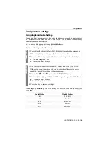
Page 16: ...l lowing pages How to end the setup mode without performing a function Press ESC to end the setup mode NOTE Only one setup function can be performed after the calling of the setup mode If you want to...

Page 17: ...connection in the terminal emulator and enter the following settings Bits per second 115 200 or 9 600 see page 25 Data bits 8 Parity none Stop bits 1 Flow control none 3 Use the provided data cable Up...

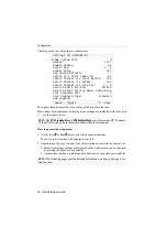
Page 18: ...by pressing the Space key repeatedly A menu item that has a sub dialogue available can be opened by pressing Enter Settings for DVIMUX4 DL Show System Info Hotkey Ctrl Double Hotkey NO Select Key 1 4...

Page 19: ...mode If the hotkey delay is active press the key combination for seven seconds 2 Press one of the setup keys listed below to enable single or double hotkeys S enables single hotkeys A disables double...

Page 20: ...the hotkey delay is active press the key combination for seven seconds 2 Press one of the setup keys listed below to enable a certain hotkey Ctrl enables Ctrl hotkey Alt enables Alt hotkey Alt Gr enab...

Page 21: ...ress one of the setup keys listed below to activate the desired double hotkey Ctrl enables Ctrl Shift double hotkey Alt enables Alt Shift double hotkey Alt Gr enables Alt Gr Ctrl double hotkey Win ena...

Page 22: ...of select keys to switch the computers 1 to 4 1 enables select keys 1 2 3 4 NUM 1 enables select keys NUM 1 NUM 3 NUM 4 Z enables select keys A B C D F1 enables select keys F1 F2 F3 F4 Setup Menu 1 Us...

Page 23: ...e the setup mode If the hotkey delay is active press the key combination for seven seconds 2 Press one of the setup keys listed below to disable enable the hotkey delay 7 enables hotkey delay 8 disabl...

Page 24: ...otkey delay is active press the key combination for seven seconds 2 Press the setup key listed below to reset the default settings D resets default settings Setup Menu 1 Use the terminal emulator to e...

Page 25: ...1 Use the terminal emulator to establish a connection to the KVM switch If the setup menu is not displayed the Switch mode of the service port is enabled Enter to change to the setup menu 2 Use the A...

Page 26: ...TE Use the setup menu to de activate the switching via hotkeys Setup Menu 1 Use the terminal emulator to establish a connection to the KVM switch and connect the serial data cable to the Service socke...

Page 27: ...sabled in the default settings IMPORTANT The active step keys are dependent on the selected select keys see page 19 The following table lists the step keys depending on the active select keys Select k...

Page 28: ...he bit rate of the Service port of the KVM switch IMPORTANT Transmitter and receiver of the data must use the same bitrate to ensure successful communication between the terminal emulator or a serial...

Page 29: ...T Depending on the purpose of use the KVM extender distinguishes between the modes listed below ADVICE The activated mode when starting the KVM extender can be changed anytime during operation By ente...

Page 30: ...ds How to select the USB keyboard type NOTE The USB keyboard type can only be changed in the setup menu Setup Menu 1 Use the terminal emulator to establish a connection to the KVM switch If the setup...

Page 31: ...performed by using the key combinations listed below Key combination Solaris Shortcut Key of the Sun keyboard Ctrl Alt F2 Again Ctrl Alt F3 Props Ctrl Alt F4 Undo Ctrl Alt F5 Front Ctrl Alt F6 Copy C...

Page 32: ...A210 0111 DVIMUX4 DL MC4 PS 2 RM CABLE SETS A610 0117 CPU DVID DL PL 2 A610 0121 CPU DVID DL PL 5 A610 0133 CPU DVIA PL 2 A610 0137 CPU DVIA PL 5 KVM SWITCHES A210 0099 DVIMUX4 DL USB A210 0101 DVIMU...

Page 33: ...4 Connection with optional cable sets at the device Interfaces for computer Video see variant features USB 4 USB B socket Audio 4 3 5 mm jack plug Line In 4 3 5 mm jack plug Line Out Video Signal type...

Page 34: ...for console Video 2 DVI I socket Interfaces for computer Video 4 2 DVI I sockets Power supply Current consumption max 160mA 240VAC 370mA 100VAC Power consumption max 22 6W 240VAC 22 3W 100VAC Casing...

Page 35: ...e Video 4 DVI I socket Interfaces for computer Video 4 4 DVI I sockets Power supply Current consumption max 233mA 240VAC 611mA 100VAC Power consumption max 33 8W 240VAC 34 3W 100VAC Casing Dimensions...

Page 36: ...Guntermann Drunck GmbH Dortmunder Str 4a 57234 Wilnsdorf Germany Phone 49 2739 8901 100 Fax 49 2739 8901 120 http www GDsys de sales GDsys de A9200088...

Reviews: