background image

Status displays

8

 · G&D MultiPower-6-NT

Status displays

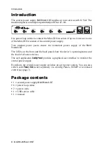
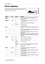
The LEDs on the front and the back panel of the 

central power supply show the device status and 

the load of active devices.

Section

LED

Status

Meaning

Ident.

on

On as soon as the LED has been activated via


web application.

Network

yellow

on

The connection to the network has been success-

fully established.

off

A connection could not be established.

green

flickering

Network activity.

off

No network activity

Load

The load of the active devices is displayed in an LED 

scale.
Four green and two yellow LEDs highlight the reach-

ing of the maximum load.
If the maximum load is exceeded, one or two red 

LEDs light up.

Note:

 If one or two red LEDs indicate that the temper-

ature within the device is too high, make sure to cool 

the device. 

Status

Ready

on

Device is ready for operation.

off

Device is not ready for operation.

System

green

Device is ready for operation.

blinking,


green

Executing update.

fast blinking,


green

Device is reset to default settings after pushing the 

Reset button for a long time.

red

Internal error

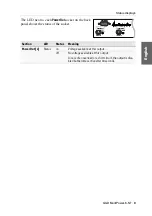
Power

Red.

on

The power pack is turned on and supplies the 

required voltage.

off

The power pack is turned off, or there is no connec-

tion to the mains.

Main

on

The power pack is turned on and supplies the 

required voltage.

off

The power pack is turned off, or there is no connec-

tion to the mains.

Network

Ident.

Ready

System

Status Power

Red.

Main

Load

Summary of Contents for MultiPower-6-NT

Page 1: ...Guntermann Drunck GmbH www gdsys de G D MultiPower 6 NT A9100287 1 20 Installationsanleitung DE EN Installation Guide ...

Page 2: ...ss G D übernimmt keine Gewährleistung für Geräte die nicht bestimmungsgemäß eingesetzt wurden nicht autorisiert repariert oder modifiziert wurden schwere äußere Beschädigungen aufweisen welche nicht bei Lieferungserhalt angezeigt wurden durch Fremdzubehör beschädigt wurden G D haftet nicht für Folgeschäden jeglicher Art die möglicherweise durch den Einsatz der Produkte entstehen können Warenzeiche...

Page 3: ...zt Hochfrequenzenergie und kann diese ausstrahlen Wenn es nicht gemäß der Anleitung installiert wird kann es Funkstörungen ver ursachen Es wird jedoch keinerlei Garantie dafür übernommen dass die Störun gen bei einer bestimmten Installation nicht auftreten Wenn dieses Gerät Störungen beim Rundfunk oder Fernsehempfang verursacht was durch Aus und Einschalten des Geräts ermittelt werden kann beheben...

Page 4: ...balen Netzwerkeinstellungen 12 Anschluss der zentralen Stromversorgung an das lokale Netzwerk 12 Start der Webapplikation 13 XML Steuerung der zentralen Stromversorgung 14 Aufbau eines gültigen XML Dokuments 14 Auswahl der Geräte 14 Verwendung von Geräte IDs 15 Antworten und Meldungen des G D Gerätes 15 Antworten des Gerätes 15 Meldungen des Geräts 16 Mehrere Befehle in einem XML Dokument kombinie...

Page 5: ...nected from all power sources Disconnect all power plugs and all power supplies of the device Débranchez toutes les sources d alimentation Avant l installation assurez vous que l appareil a été débranché de toutes les sources d alimentation Débranchez toutes les fiches d alimentation et toutes les alimenta tions électrique de l appareil Vorsicht vor Stromschlägen Um das Risiko eines Stromschlags z...

Page 6: ...tgelieferten oder in der Bedienungsanlei tung aufgeführten Netzteil Betreiben Sie das Gerät ausschließlich im vorgesehenen Einsatzbereich Die Geräte sind für eine Verwendung im Innenbereich ausgelegt Vermeiden Sie extreme Kälte Hitze oder Feuchtigkeit Die Geräte sind nicht für die Verwendung in gefährlichen Umgebungen zugelassen ...

Page 7: ...rauchte Batterien dürfen nicht in den Hausmüll geworfen werden Beachten Sie die gültigen Vorschriften zur Entsorgung elektronischer Produkte CAUTION Risk of explosion if the battery is replaced by an incorrect battery type Dispose of used batteries in an environmentally friendly manner Do not dispose of batteries in municipal waste Check local regulations for the disposal of electronic products AT...

Page 8: ...ie Last der eingeschalteten Geräte Mit der Webapplikation Config Panel steht eine grafische Benutzeroberfläche zur Überwachung der zentralen Stromversorgung zur Verfügung In der Standardeinstellung schaltet die zentrale Stromversorgung alle 6 Power Out lets ein Sie haben die Möglichkeit jede Power Out Buchse separat via Config Panel via SNMP oder via textbasierter Steuerung zu schalten s Seite 6 L...

Page 9: ...kdose eines anderen Stromkreises Inbetriebnahme 1 Schalten Sie den Netzschalter des internen Netzteils Main Power ein 2 Schalten Sie ggf den Netzschalter des internen Netzteils Red Power ein HINWEIS Maximal sechs Geräte können mit einem Strom von 12 Volt durch die zentrale Stromversorgung versorgt werden Die maximal zulässige Stromaufnahme pro Gerät beträgt 1 6 A HINWEIS Nach dem Einschalten des G...

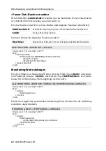
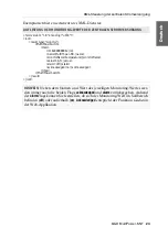
Page 10: ... auf die umzuschaltende Power Out Buchse Schaltung via SNMP So schalten Sie eine Power Out Buchse via SNMP Setzen Sie das Managed Object outletStatus der zu schaltenden Power Out Buchse über die SNMP Managementstation auf 0 off 1 on oder 2 resetting Schaltung via textbasierter Steuerung Detaillierte Informationen zur Verwendung der XML Steuerung s Seite 14 ff und die Befehle zur Schaltung einer Po...

Page 11: ...ten Je ein Relais signalisiert über einen Wechsler den Status der Stromversorgung Bei unterbrochener Spannungsversorgung ist der Wechsler auf Pin 3 Main Power bzw Pin 8 Red Power geschaltet Bei anliegender Spannung schaltet der Wechsler auf Pin 4 Main Power bzw Pin 9 Red Power um TIPP Verwenden Sie die Box Web IO 2x Digital PoE um den Status der Netzteile über eine Netzwerkverbindung via SNMP Trap...

Page 12: ... maximal zulässige Last überschritten leuchten zusätzliche eine bzw zwei rote LEDs Hinweis Eine hohe Temperatur im Geräteinneren wirkt sich nachteilig auf die Leistung des Gerätes aus Kühlen Sie das Gerät falls ein oder zwei rote LEDs im Normalbetrieb leuchten Status Ready an Gerät betriebsbereit aus Gerät nicht betriebsbereit System grün Gerät betriebsbereit blinkt grün Update wird ausgeführt bli...

Page 13: ...eich LED Status Bedeutung Power Out x Status an Die Spannung steht an diesem Ausgang bereit aus An diesem Ausgang steht keine Spannung zur Verfügung Im Falle einer Überlast oder eines Kurzschlusses wird der Ausgang abgeschaltet und nach 10 Sekunden wieder akti viert Power Status Power Out 1 12VDC 1 6A Power Out 2 Status 12VDC 1 6A MULTIPOWER 6 NT ...

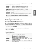
Page 14: ...gung Verwenden Sie hierzu ein Twisted Pair Kabel der Kategorie 5 oder höher 2 Stellen Sie sicher dass die IP Adresse der Netwerkschnittstelle des Rechners Teil des Subnetzes ist welchem auch die IP Adresse des Gerätes angehört 3 Schalten Sie die zentrale Stromversorgung ein Start der Webapplikation So konfigurieren Sie die Einstellungen einer Netzwerkschnittstelle 1 Starten Sie den Webbrowser des ...

Page 15: ... des Administratorkontos Die voreingestellten Zugangsdaten zum Administratorkonto lauten Benutzername Admin Passwort siehe Login Information auf dem Etikett an der Geräteunterseite HINWEIS Das voreingestellte Admin Passwort von Geräten mit Produktionsdatum vor März 2020 lautet 4658 HINWEIS Der Link Local Adressraum 169 254 0 0 16 ist gemäß RFC 3330 für die interne Kommunikation zwischen Geräten re...

Page 16: ...etzwerk an 1 Entfernen Sie die Twisted Pair Kabelverbindung zwischen dem Rechner und der zentralen Stromversorgung 2 Integrieren Sie die zentrale Stromversorgung in das lokale Netzwerk Betriebsmodus Wählen Sie den gewünschten Betriebsmodus Statisch Verwendung von statischen Einstellungen DHCP Bezug der Einstellungen von einem DHCP Server Host Name Geben Sie den Host Namen des Gerätes ein Domäne Ge...

Page 17: ... den Systemvoraussetzungen der erfor derlichen Konfiguration der Netzwerkschnittstelle der MultiPower NT Geräte und zum Einsatz der Webapplikation finden Sie im separaten Handbuch Benutzername Geben Sie den Benutzernamen eines Administratorkontos ein Passwort Geben Sie das zugehörige Passwort des Administratorkontos ein WICHTIG Ändern Sie das voreingestellte Passwort des Administratorkontos Die vo...

Page 18: ...t plat ziert Ab Seite 21 werden die verschiedenen Befehle erläutert Auswahl der Geräte Die XML API bietet durchgängig die Möglichkeit Geräte nicht nur über ihre ID sondern wahlweise auch über ihren Namen anzugeben Über das Attribut type können Sie zwischen der Auswahl per ID id oder per Namen name unterscheiden Das Attribut wird von allen Befehlen unterstützt die sich auf Geräte beziehen die einen...

Page 19: ...Im Attribut type ist der Name des ausgeführten Befehls enthalten Beim Ausführen mehrerer Befehle in einem XML Dokument siehe unten können Sie so die Antwor ten den verschiedenen Befehlen zuordnen Im folgenden Beispiel wurden die Temperatur einer zentralen Stromversorgung abgefragt Die verfügbaren Informationen werden innerhalb der item Tags aufge listet ADRESSIERUNG DER ZENTRALEN STROMVERSORGUNG A...

Page 20: ...ontainer ausgegeben Hierfür werden folgende Container benutzt Fehlermeldungen werden innerhalb des Containers Error ausgegeben Warnungen werden innerhalb des Containers Warning ausgegeben Erfolgsmeldungen und allgemeine Meldungen die nicht zu den oben aufgeführten Kategorien passen werden innerhalb des Containers commandStatus ausgegeben AUFBAU EINES FEHLERDOKUMENTS xml version 1 0 encoding utf 8 ...

Page 21: ...nitialisierungsvektor verschlüsselt sind Passwort Verschlüsselung In diesem Modus werden nur die Passwörter der Benutzer konten in den XML Antworten des G D Geräts verschlüsselt Hierfür wird ein Subset der XML Encryption s Seite 19 eingesetzt In XML Befehlen können Passwörter in diesem Modus wahlweise verschlüsselt empfohlen oder im Klartext an das Gerät versendet werden Beide Verschlüsselungsarte...

Page 22: ... UPD über welches die XML Kommunikation abgewickelt wird Port Geben Sie den Port an über welchen die XML Kommuni kation abgewickelt wird Die Ports 80 443 und 27996 werden für andere Dienste ver wendet Sie sind für die XML Steuerung nicht verfügbar Status Wählen Sie ob der Zugang aktiviert oder deaktiviert ist Verschlüsselung Folgende Arten der Verschlüsselung werden unterstützt unverschlüsselt Wäh...

Page 23: ...nc ersetzt In diesem Container wird der Container CipherData erwartet der wiederum den Container CipherValue enthält Der verschlüsselte Datenblock CipherValue besteht aus der Kombination von Initiali sierungsvektor und verschlüsseltem Text mit Padding in BASE64 kodierter Darstellung HINWEIS In den XML Anfragen können die Passwörter bei aktivierter Passwort Verschlüsselung wahlweise verschlüsselt e...

Page 24: ... das letzte Byte des Padding die Anzahl hinzugefügter Füllbytes angibt Die Füllbytes selbst sind zufällig zu wählen Der Initialisierungsvektor wird für Stromchiffren hier CBC benötigt Er wird im Verschlüsselungsmodus Passwort Verschlüsselung zufällig gewählt Die Größe ent spricht der Blockgröße der zu Grunde liegenden Verschlüsselung 8 Bytes IV encrypted data plain text padding Initialization Vect...

Page 25: ...ür die Ausschaltung einer Power Out Buchse sind folgende Parameter erforder lich MultiPowerSwitch Zentrale Stromversorgung deren Power Out Buchse eingeschaltet wird outlet Nr der Power Out Buchse EINSCHALTEN EINER POWER OUT BUCHSE xml version 1 0 encoding utf 8 root powerupoutlet MultiPowerSwitch 0x0000000A MultiPowerSwitch Outlet 1 Outlet powerupoutlet root MultiPowerSwitch Zentrale Stromversorgu...

Page 26: ...h die Angabe des gewünschten Monitoring Wertes können Sie die Auflistung zusätzlich eingeschränken MultiPowerSwitch Zentrale Stromversorgung deren Power Out Buchse resettet wird outlet Nr der Power Out Buchse ResetDelay Angabe eines Zeitraums in ms zur Verzögerung des Wiedereinschaltens RESETTEN EINER POWER OUT BUCHSE xml version 1 0 encoding utf 8 root powerresetoutlet MultiPowerSwitch 0x0000000A...

Page 27: ...name MultiPower NT name monitorName Temperature monitorName value 36 5 value alarm off alarm acknowledged no acknowledged item MultiPowerSwitch result root HINWEIS Neben dem Namen und Wert des jeweiligen Monitoring Wertes wer den immer auch die beiden Flags acknowledged und alarm zurückgegeben Anhand der alarmFlags können Sie feststellen ob sich der Monitoring Wert im Sollbereich befinden off oder...

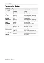
Page 28: ...0 50Hz 1 4 0 6 A redundante Stromversorgung Typ internes Netzteil Anschluss 1 Kaltgerätestecker IEC 320 C14 Stromaufnahme 100 240 VAC 60 50Hz 1 4 0 6 A Sonstige Schnittstellen Netzwerk 1 RJ45 Buchse Service 1 Mini USB Buchse Typ B Gehäuse Material Aluminium eloxiert Maße B H T 19 1HE 154 5 mm Gewicht ca 1900 g Einsatzumgebung Temperatur 5 bis 45 C Luftfeuchte 20 bis 80 nicht kondensierend Lagerumg...

Page 29: ... Deutsch ...

Page 30: ... will not provide warranty for devices that Are not used as intended Are repaired or modified by unauthorized personnel Show severe external damages that was not reported on the receipt of goods Have been damaged by non G D accessories G D will not be liable for any consequential damages that could occur from using the products Proof of trademark All product and company names mentioned in this man...

Page 31: ... equipment generates uses and can radiate radio frequency energy and if not installed and used in accordance with the instructions may cause harmful inter ference to radio communications However there is no guarantee that interfer ence will not occur in a particular installation If this equipment does cause harmful interference to radio or television reception which can be deter mined by turning t...

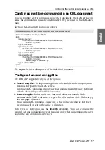
Page 32: ...1 Configuring global network settings 12 Connecting the central power supply to the local network 12 Starting web application 13 Controlling the central power supply via XML 14 Structure of a valid XML document 14 Selecting devices 14 Use of device IDs 15 Responses and messages of G D devices 15 Responses of the device 15 Device messages 16 Combining multiple commands in an XML document 17 Configu...

Page 33: ...e l appareil a été débranché de toutes les sources d alimentation Débranchez toutes les fiches d alimentation et toutes les alimenta tions électrique de l appareil Trennen Sie alle Spannungsversorgungen Stellen Sie vor der Installation sicher dass das Gerät von allen Stromquellen getrennt ist Ziehen Sie alle Netzstecker und alle Spannungsversorgungen am Gerät ab Beware of electric shocks To avoid ...

Page 34: ...te this device with the provided G D power pack or with the power pack listed in the manual Operate the device only in designated areas The devices are designed for indoor use Avoid exposure to extreme cold heat or humidity The devices are not approved for use in hazardous environments ...

Page 35: ...ot dispose of batteries in municipal waste Check local regulations for the disposal of electronic products ATTENTION Il y a danger d explosion s il y a remplacement incorrect de la batterie Mettre au rebut les batteries usagées conformêment aux instructions du fabricant et de manière écologique Les batteries usagées ne doivent pas être jetées dans les ordures ménagères Respectez les prescriptions ...

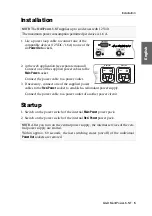
Page 36: ... the load of all active devices The web application Config Panel provides a graphical user interface to monitor the central power supply By default the central power supply switches on all 6 power outlets You can also switch each Power Out socket separately via Config Panel SNMP or text based control see page 7 Package contents 1 central power supply MultiPower 6 NT 6 power loop cables 2 power cab...

Page 37: ...t the power cable to a power outlet of another power circuit Startup 1 Switch on the power switch of the internal Main Power power pack 2 Switch on the power switch of the internal Red Power power pack NOTE The MultiPower 6 NT supplies up to six devices with 12 Volt The maximum power consumption permitted per device is 1 6 A NOTE After you turn on the central power supply the internal services of ...

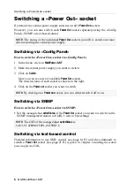
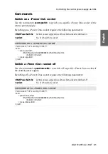
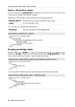
Page 38: ...ight 4 Click on the Power out socket you want to switch Switching via SNMP How to switch a Power Out socket via SNMP Set the managed object outletStatus of the Power Out socket you want to switch via the SNMP management station to 0 off 1 on or 2 resetting Switching via text based control Detailed information to use XML control see page 14 ff and the commands to switch a Power Out socket see page ...

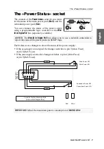
Page 39: ...h relais uses a changer to show the status of the power supply If the power supply is interrupted the changer switches to pin 3 Main Power or pin 8 Red Power If the power supply is active the changer switches to pin 4 Main Power or pin 9 Red Power ADVICE The Web IO 2x Digital PoE box allows you to use a network connection to report the status of the power packs via SNMP traps IMPORTANT Mind the ma...

Page 40: ...the maximum load is exceeded one or two red LEDs light up Note If one or two red LEDs indicate that the temper ature within the device is too high make sure to cool the device Status Ready on Device is ready for operation off Device is not ready for operation System green Device is ready for operation blinking green Executing update fast blinking green Device is reset to default settings after pus...

Page 41: ...at this output off No voltage available at this output In case of an overload or a short circuit the output is disa bled but becomes active after 10 seconds Power Status Power Out 1 12VDC 1 6A Power Out 2 Status 12VDC 1 6A MULTIPOWER 6 NT Power Status Power Out 1 12VDC 1 6A Power Out 2 Status 12VDC 1 6A MULTIPOWER 6 NT Power Status Power Out 1 12VDC 1 6A Power Out 2 Status 12VDC 1 6A MULTIPOWER 6 ...

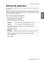
Page 42: ...t the network interface of any computer to the central power supply s Network interface 2 Make sure that the IP address of the computer s network interface is part of the subnet to which the IP address of the device belongs 3 Turn on the central power supply Starting the web application How to configure the settings of a network interface 1 Start the computer s web browser and enter the URL 192 16...

Page 43: ...tor account s default password The default access data is Username Admin Password see login information on the label on the bottom of the device NOTE The default admin password for devices manufactured before March 2020 is 4658 NOTE The Link Local address space 169 254 0 0 0 16 is reserved for internal com munication between devices according to RFC 3330 It is not possible to assign an IP address ...

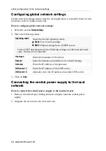
Page 44: ...supply to the local network 1 Remove the twisted pair cabling between computer and the central power supply 2 Integrate the device into the local network Operating mode Enter the desired operating mode Static Use of static settings DHCP Obtain settings from a DHCP server Hostname Enter the hostname of the device Domain Enter the domain to which the device should belong Gateway Enter the IP address...

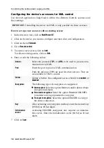
Page 45: ... Login NOTE The separate manual provides information about system requirements the required configuration of the network interface at the MultiPower NT devices and the operation of the web application Username Enter the username of an administrator account Password Enter the password of the administrator account IMPORTANT Change the administrator account s default password The default access data ...

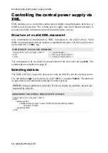
Page 46: ...ecuted are placed between the start and end tag root The commands are described on page 21 Selecting devices The XML API lets you specify devices not only by their ID but also by their name Use the attribute type to select devices via ID id or via name name The attribute is supported by all commands referring to named devices STRUCTURE OF A VALID XML DOCUMENT xml version 1 0 encoding utf 8 optiona...

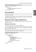
Page 47: ... in a result tag The attribute type includes the name of the executed command When executing several commands within the same XML document see below you can assign the responses to different commands In the following example the temperature of a central power supply was queried The available information is listed within the item tags ADDRESSING THE CENTRAL POWER SUPPLY BY ID xml version 1 0 encodi...

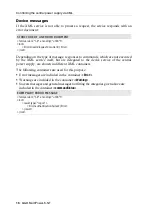
Page 48: ...supply are shown in different XML containers The following containers are used for this purpose Error messages are included in the container Error Warnings are included in the container Warning Success messages and general messages not fitting the categories given above are included in the container commandStatus STRUCTURE OF AN ERROR DOCUMENT xml version 1 0 encoding utf 8 root Error Invalid requ...

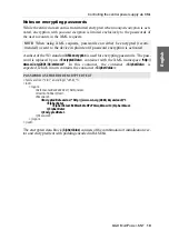
Page 49: ...ation vector Password encryption In this mode only passwords of user accounts in XML responses of the G D device are encrypted For this a subset of the XML encryp tion see page 19 is used When using XML commands passwords in this mode can either be encrypted recommended or sent to the device in plain text Both types of encryption use the CBC 3DES algorithm You can configure the required key and in...

Page 50: ...ccess Select the protocol TCP or UPD to be used to process com munication via XML Port Enter the port to process XML communication Ports 80 443 und 27996 are used for other services They are not available for XML control Status Define whether the configured access should be enabled or disabled Encryption The following types of encryption are supported Unencrypted Select the option None to transfer...

Page 51: ...04 xmlenc In this container the container CipherData is expected which in turn contains the container CipherValue The encrypted data block CipherValue consists of the combination of initialization vec tor and encrypted text with padding encoded in BASE64 NOTE When using XML requests passwords can either be encrypted recom mended or sent to the device in plain text if password encryption is activat...

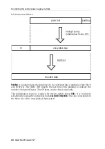
Page 52: ...e last byte of the padding to indicate the number of added fill bytes The fill bytes can be chosen randomly The initialization vector is required for stream ciphers here CBC It is randomly selected when using the encryption mode password encryption The size corresponds to the block size of the encryption 8 bytes used IV encrypted data plain text padding Initialization Vector IV encrypt using BASE6...

Page 53: ...ly Switching off a Power Out socket requires the following parameters MultiPowerSwitch Central power supply whose Power Out socketis switched on outlet No of Power Out socket SWITCHING ON A POWER OUT SOCKET xml version 1 0 encoding utf 8 root powerupoutlet MultiPowerSwitch 0x0000000A MultiPowerSwitch Outlet 1 Outlet powerupoutlet root MultiPowerSwitch Central power supply whose Power Out socketis ...

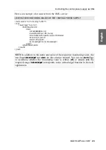
Page 54: ...ring values You can further restrict the list by specifying the desired monitoring value MultiPowerSwitch Central power supply whose Power Out socket is reset outlet No of Power Out socket ResetDelay Specifies a time period in ms to delay the reset RESETTING A POWER OUT SOCKET xml version 1 0 encoding utf 8 root powerresetoutlet MultiPowerSwitch 0x0000000A MultiPowerSwitch Outlet 1 Outlet ResetDel...

Page 55: ... name MultiPower NT name monitorName Temperature monitorName value 36 5 value alarm off alarm acknowledged no acknowledged item MultiPowerSwitch result root NOTE In addition to the name and value of the respective monitoring value the two flags acknowledged and alarm are also always returned You can use alarm flags to determine whether the monitoring value is within off or outside on the required ...

Page 56: ...z 1 4 0 6 A Redundant power supply Type Internal power pack Connector 1 IEC plug IEC 320 C14 Power consumption 100 240 VAC 60 50Hz 1 4 0 6 A Other interfaces Network 1 RJ 45 socket Service 1 Mini USB socket type B Housing Material Anodised aluminium Dimensions W H D 19 1U 154 5 mm Weight Approx 1900 g Operating environment Temperature 5 to 45 C Air humidity 20 to 80 non condensing Storage environm...

Page 57: ... English ...

Page 58: ... ...

Page 59: ... English ...

Page 60: ...Obere Leimbach 9 57074 Siegen Germany www gdsys de sales gdsys de Das Handbuch wird fortlaufend aktualisiert und im Internet veröffentlicht The manual is constantly updated and available on our website https gdsys de A9100287 ...

Reviews: