background image

INSTALLATION GUIDE • USER MANUAL 

VERTICAL AIR SERIES


2

5

COMPRESSOR NAMEPLATE 

The compressor nameplate provides the following information: 

Unit model and size descriptor

Unit serial number

Identifies unit electrical

COMPRESSOR INFORMATION 

OIL LEVEL 

To check compressor oil level, refer to the label near the compressor sight glass. The compressor(s) must be off. Wait 

three minutes. Compressor oil level should be within the range indicated on the sticker; close to half full. When 

adding oil, always use a fresh can of POE 32 or POE 68 per the compressor data plate. 

NOTICE:

 Never reuse oil or use oil from an unsealed container. 

OIL TESTING 

Use the oil test kit provided or recommended by the testing laboratory. Note that the POE oil used in this product is 

very hygroscopic and easily absorbs and retains moisture. The acceptable moisture content is less than 100 ppm and 

acceptable acid level is less than 0.5 TAN. Note that refrigerant and moisture is very difficult to remove from this oil 

using vacuum. Also note that once the seal on a container of POE oil is opened, the oil must be used. Any unused oil 

should be discarded. 

In the event of a compressor failure, always test the oil with an acid test kit and determine whether the compressor 

failure was mechanical or electrical. This is important because it dictates correct cleanup procedure. 

COMPRESSOR OPERATIONAL PUMP DOWN 

The  operational  pump  down  is  used  to  manage  the  refrigerant  charge  and  prevent  liquid  slugging  into  the 

compressors, oil dilution and oil starvation. The pump down occurs during all normal shut- down conditions. The 

electronic expansion valve will close. 

The operational pump down sequence will end when the suction pressure drops below the operational pump down 

set point. 

ELECTRICAL COMPRESSOR FAILURE 

Replace the failed compressor and add a suction filter with cleanup cores and change the liquid line filter drier. 

Change filters and oil until the oil no longer tests acidic. See "Oil Testing." 

COMPRESSOR MOTOR MEGGING 

Motor megging  determines  the  electrical integrity  of  the  compressor  motor  winding  insulation.  Use  a  500-volt 

megger. A less than 1 meg-ohm reading is acceptable and 1000 ohms per nameplate volts is required to safely start 

the compressor. 

COMPRESSOR CURRENT IMBALANCE 

Normal current imbalance could be 4 to 15 percent with balanced voltage due to motor design. Each phase should 

register 0.3  to  1.0  ohms and  each  phase should be within  7  percent of the other  two  phases.  Phase to  ground 

resistance must be infinity. 

NOTICE:

 Maximum allowable voltage imbalance is 2 percent. 


G&D CHILLERS, INC.  


GD-VA-R2022C
Summary of Contents for VERTICAL AIR Series

Page 1: ...1 800 555 0973 INFO GDCHILLERS COM GDCHILLERS COM INSTALLATION VIDEOS CHILLERINSTALLATION GUIDE USER MANUAL VERTICAL AIR SERIES...

Page 2: ...I 2 VERTICAL AIR SERIES CHILLER MANUAL 2022 G D CHILLERS INC ALL RIGHTS RESERVED...

Page 3: ...LER DESCRIPTION 7 INSALLATION OVERVIEW 8 INSTALLATION REQUIREMENTS AND CONTRACTOR RESPONSIBILITIES 9 INSTALLER SUPPLIED COMPONENTS 9 CHILLER INSTALLATION MECHANICAL 9 PIPING RECOMMENDATIONS 11 ELECTRI...

Page 4: ...HECKLIST 22 TERA 23 MODEL INFORMATION 24 UNIT NAMEPLATE 24 COMPRESSOR NAMEPLATE 25 COMPRESSOR INFORMATION 25 COMPRESSOR REPLACEMENT 26 POWER SUPPLY WIRING 28 MAINTENANCE 30 MAINTENANCE CHECKLIST 33 TR...

Page 5: ...the main office at 1 800 555 0973 The voicemail recording will provide contact information for the emergency on call service technician INSTALLATION VIDEO LINKS Visit the following pages for installat...

Page 6: ...the damage did not occur after delivery Notify the carrier s terminal of the damage immediately by phone and by mail Request an immediate joint inspection of the damage with the carrier and the consi...

Page 7: ...pressure design allows circuiting back to tank without damage to system or pump Copper and bronze construction REFRIGERANT PIPING Type L ACR copper Liquid line filter drier sight glass moisture indic...

Page 8: ...copper wire Size wire and according to any all applicable local and national codes Refer to chart to the right for proper torque values Refer to spec sticker on control panel for all electrical rating...

Page 9: ...l interconnecting wiring in conduit for field supplied devices Unit disconnect fused CHILLER INSTALLATION MECHANICAL LOCATION REQUIREMENTS SOUND CONSIDERATIONS Refer to G D data sheet for sound data L...

Page 10: ...voir Be sure to provide additional vents at high points in the piping to bleed air from the chilled fluid system Do not pressurize reservoir Install necessary pressure gauges to monitor the entering a...

Page 11: ...enclosure Use closed cell foam insulation Install protective cladding Materials Schedule 80 PVC or ABS typical for cold glycol water systems Verify operating temperatures High temp systems may requir...

Page 12: ...UNION BALL VALVE TRUE UNION BALL VALVE SUPPLY RETURN DETAIL F SCALE 1 11 PIPE REDUCER TRUE UNION BALL VALVE SCH 80 PVC PIPE ELECTRONIC ACTUATED VALVE CHECK VALVE SUPPLY RETURN AIR BLEED VALVE VACUUM...

Page 13: ...wiring 30V in conduit with conductors carrying more than 30 volts SEQUENCE OF OPERATION 1 Chiller supply and return ball valves should always be open during normal operation 2 Fluid bypass valve is f...

Page 14: ...chiller products The chiller uses brazed plate evaporators and an air cooled condenser The compressors use suction gas cooled motors and an oil management system to provide almost oil free refrigeran...

Page 15: ...pump pressure set point b Press ENTER button to navigate to numerical readout and adjust with UP and DOWN to set pump pressure Please note that pressure setpoints are preset Info screens 1 Ensure you...

Page 16: ...24 59 269 3 74 8 6 15 8 9 9 A B 521 C D 2 E 03 15 4 8 8 F G15 H9 2 I1 J K LM I G K NO 5 G K NO JP MQ R L C C F S LMT G3 9 2 521 O U 8 9 V 8 2W 8 8 Q F XY Y Y F Q N F Z F N S N F F L F N N T NLLQC 9M...

Page 17: ...x w t 0x M K B A A B B G 2 6 P 2 rH 53pg A K g1 _ L G B G 6 k z 3 2 6A B H 2 r A K 53pg I G B A I K G BG 2G P 2 2 B G A K g1 _ K G B 26 gG C A EGK KK G A B B A K K 2 C AA 6 G 3 J 3 4 M s l k 12 P A L...

Page 18: ...START UP PROCEDURES POWER UP When power is applied to the chiller the HMI will boot up to the main screen The chiller will start if both the control power switch and the chiller start stop switch are...

Page 19: ...ula to maintain the fluid temperature as close to the set point as possible At times the compressors may continue to run even if the fluid temperature is below the set point This is normal Note Once t...

Page 20: ...e servicing could result in death or serious injury FREEZE PROTECTION The chiller system must be protected from freezing by use of a freeze inhibitor The solution must be strong enough to provide prot...

Page 21: ...irm glycol pressure shows 20 PSI using both the Carel controller and the manual pressure gauge located on the process pump discharge line refer to 9 if a lower pump pressure is required 6 Open the sup...

Page 22: ...ROTATION GLYCOL PRESSURE COMPRESSOR A COMPRESSOR B COMPRESSOR C COMPRESSOR D CRANK CASE HEATER ENGERGIZED 4 HOURS COMPRESSOR OIL LEVEL MOTOR AMPS L1 L1 L1 L1 L2 L2 L2 L2 L3 L3 L3 L3 SUPERHEAT F 30 F...

Page 23: ...m integrates with your chiller to monitor and remotely display chiller parameters for glycol supply and return temperatures pressure and flow It also sends SMS text alerts for any abnormal conditions...

Page 24: ...fficient temperature control Each refrigerant circuit is provided with a removable core filter drier sight glass electronic expansion valve and charging valves The evaporator is a brazed plate or shel...

Page 25: ...t kit and determine whether the compressor failure was mechanical or electrical This is important because it dictates correct cleanup procedure COMPRESSOR OPERATIONAL PUMP DOWN The operational pump do...

Page 26: ...n to the compressor s COMPRESSOR ELECTRICAL TERMINAL BOX Be sure to protect the terminal box and all wiring when un brazing or brazing compressor refrigerant piping connections COMPRESSOR REPLACEMENT...

Page 27: ...BB VFD 1 Press the menu button 2 Arrow to FAULT LOGGER 3 Press the top right button indicating ENTER NOTICE DO NOT CLEAR FAULTS WITHOUT DOCUMENTING FAULT DESCRIPTION AND CONTACTING G D CHILLERS TECHNI...

Page 28: ...d one hour open time Plug the open refrigerant line to minimize moisture absorption Always change the liquid line filter drier Evacuate the system to 500 microns or below Remove pressure transducer an...

Page 29: ...Excessive voltage imbalance between the phases of a three phase system can cause motors to overheat and eventually fail The maximum allowable imbalance is 2 percent UNIT VOLTAGE PHASING It is importa...

Page 30: ...ottom of compressor monthly Inspect for any oil leaks Verify pump function quarterly Confirm glycol supply pressure Listen for abnormal sounds from the pump Verify thermostat function quarterly Check...

Page 31: ...late heat exchanger BPHX evaporators with factory installed electronic flow switch that is positioned in the evaporator fluid outlet pipe Note Strainer maintenance is critical to proper operation and...

Page 32: ...A or R448A refrigerant Use only manifold gauge sets designed for use with R404A or R448A refrigerant Use only refrigerant recovery units and cylinders designed for use with R404A or R448A refrigerant...

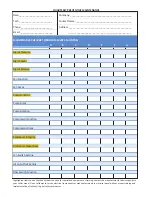
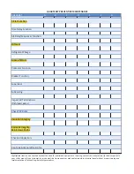
Page 33: ..._________________ MAINTENANCE CHECKLIST PERFORM EVERY 3 MONTHS A B C D E F G Glycol Pressure Glycol Level Glycol Mixture Fan Function Fan Amps Pump Function Pump Amps Pump Rotation Compressor Function...

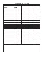
Page 34: ...Function Breaker Function SuperHeat Check All Capacitors Inspect All Terminations Tightness Burns Check TXV Bulbs Insulation Integrity Cosmetic Integrity Skin Screws Knobs Cap Tube Silicone Wire Zip...

Page 35: ...PARTS LIST Quantity Additional Comments Yh Zd Z z WZ s Ed s D Ed E E...

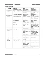
Page 36: ...d recharge Plugged filter drier Replace filter drier Insufficient subcooling Check condenser subcooling circuit 4 Suction pressure too high Glycol temperature will not reach set point Excessive load o...

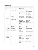
Page 37: ...Restart 3 ph compressor by switching 2 phases replace if it does not restart 9 Compressor starts but start relay does not drop out High running current overload trips Incorrect wiring of start compon...

Page 38: ...ve LLSV Replace LLSV Leaking compressor valves Replace compressor Undercharged system Check for leaks and recharge 13 Internal pressure safety valve IPRV opens Refrigerant trapped in compressor Discha...

Page 39: ...t 1 Parameter Cb17 AL108 Circuit 1 Envelope High suction pressure A Stop circuit 1 Parameter Cb17 AL109 Circuit 1 Envelope Low compression ratio A Stop circuit 1 Parameter Cb17 AL110 Circuit 1 Envelop...

Page 40: ...sure A Stop circuit 2 Parameter Cb18 AL211 Circuit 2 Envelope Low discharge pressure A Stop circuit 2 Parameter Cb17 AL212 Circuit 2 Envelope Low suction pressure A Stop circuit 2 Parameter Cb17 AL213...

Page 41: ...N B C C D S C U N C C S D N G N Y D S F D M N X N H E G M E Z E A N O C C S D N G N Y D S F D D U A E G E D D N U E N M E Y M N X D U N C N F N G A B Y N V N T B C D N H B D U A E G P _ V _ RX D K a...

Page 42: ...is longer Any upgrade to the original product will be covered only for the duration of the original warranty period EXCLUSIONS This warranty does not cover for example abuse accident acts of God consu...

Page 43: ...CABLE LAW G D CHILLERS INC DOES NOT WARRANT THAT THE OPERATION OF ANY PRODUCTS COVERED UNDER THIS LIMITED WARRANTY WILL MEET YOUR REQUIREMENTS OR THIRD PARTY SERVICES BE UNINTERRUPTED ERROR FREE OR TH...

Page 44: ...INSTALLATION GUIDE USER MANUAL SINGLE DUAL STAGE MODELS 44 G D Chillers welcomes any and all questions or concerns We can be reached at 800 555 0973 or 541 345 3903...

Reviews: