Installation
7
· G&D VisionXS-IP-C-DP-UHR
Installing the computer module
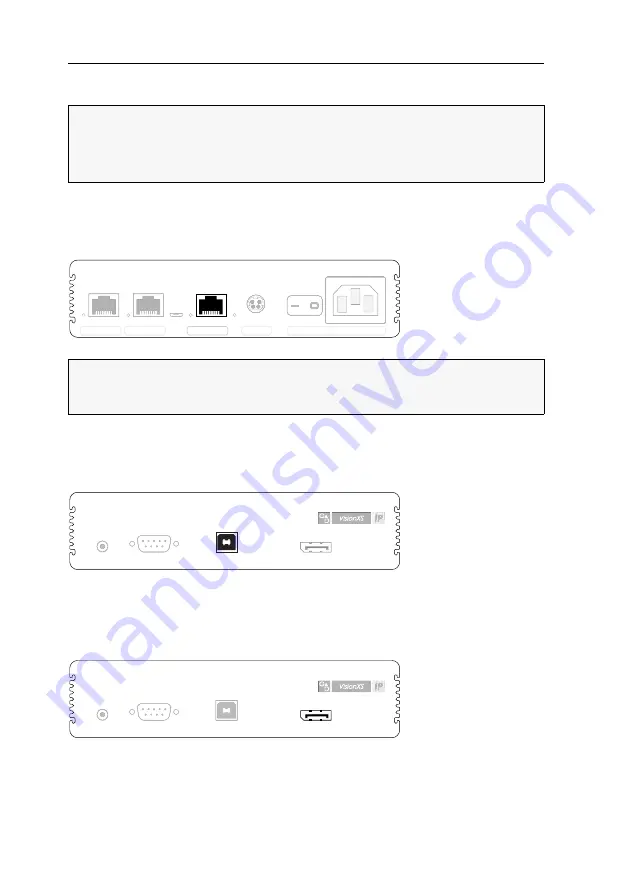
The computer, whose signals are transmitted to the remote console, is connected to
the
VisionXS-IP-CPU
computer module.
Establishing a connection to a local management network
Network:
Insert a category 5 twisted pair cable (or better), which is available as acces-
sory. Connect the other end of the cable to the local network.
Connecting keyboard and mouse signals of the local computer
USB CPU:
Use the
USB-AM/BM-2
cable to connect one of the computer’s USB inter-
faces to this interface.
Connecting the computer’s video output
DP CPU:
Use the
DP-Cable-M/M-2
cable to connect the computer’s video output to
this interface.
NOTE:
All device variants of the
VisionXS-IP
series can be operated with an
external
power supply at the
Power
interface (for desktop casings:
Main Power
).
The illustrations in this chapter show the desktop variant of the device series. This
variant is additionally equipped with an
internal
power supply (
Red. Power
).
NOTE:
If desired, connect this network interface to a local network. This enables
you to access the
Config Panel
web application from this network and to send sys-
log messages to this network.
Service
Transmission 2
Transmission 1
Pwr Main Power
Red. Power
Network
Pwr Main Power
Red. Power
Service
Transmission 2
Transmission 1
Line In
Serial
USB CPU
DP CPU
Line In
Serial
DP CPU
Line In
Serial
USB CPU
DP CPU
Line In
Serial
USB CPU
Summary of Contents for VisionXS-IP-C-DP-UHR
Page 70: ......
Page 71: ...Deutsch...
Page 140: ......
Page 141: ...English...
Page 142: ......
Page 143: ...English...


