background image

STRONG. SIMPLE. COMPACT.

Rev Date 23 0610

800.285.6780   sales@ggled.net

EDGE

 INSTALLATION MANUAL PAGE 2

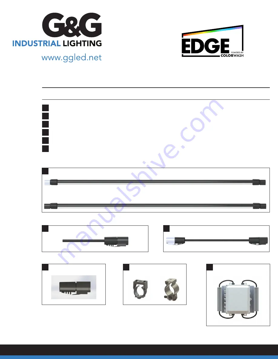
Supplied Materials

1

G&G 

EDGE

 Series Fixtures

2

Leader Cable(s)

3

Jumper Cable(s)

4

Termination Plug(s)

5

Mounting Brackets (Ceiling or Wall)

6

G&G 

EDGE

 Power/Data Translator (PDT) [Includes controls, power distribution and drivers.]

1

EDGE

 Standard Fixture

EDGE

 Leader Fixture

2

3

Leader Cable

Jumper Cable

4

Termination Plug

6

EDGE

 Power Data/Translator Box

5

Mounting Brackets

Summary of Contents for EDGE

Page 1: ...azard if left unchecked This heating can also serve as an ignition source for gasses generated by the corrosion of metals inside of the enclosure Regularly scheduled inspections are recommended to ens...

Page 2: ...es Fixtures 2 Leader Cable s 3 Jumper Cable s 4 Termination Plug s 5 Mounting Brackets Ceiling or Wall 6 G G EDGE Power Data Translator PDT Includes controls power distribution and drivers 1 EDGE Stan...

Page 3: ...U fixtures in each string have 4 pin connectors THRU fixtures have a gray connector shell on the input end and a black connector shell on the output end while LEAD fixtures have black connector shells...

Page 4: ...ds using a chalk line or laser to mark the mounting bracket locations 2 4 and 6 fixtures require at least two mounting brackets Brackets should be installed near the ends of the fixtures 8 models requ...

Page 5: ...D at the bottom of the board below the driver fuses The input circuit shall be supplied with a 20A breaker on 120V systems or a 15A breaker on 277V systems Power Data Translator PDT Board The AC Input...

Page 6: ...The B outputs 1B and 2B have a limit of 40 feet G G recommends that the split be as even as possible within these limits For example if possible split 88 feet into a 48 foot string and a 40 foot stri...

Page 7: ...be connected to output 2A Failure to make the correct connections will lead to lighting effects being generated in an erratic manner To connect the leader cables to the LED Output terminals remove 2 3...

Page 8: ...ee discrete wires in the data cable these are marked on the board next to the terminals D D and COM Optionally the RJ45 8P8C connector can be used instead of the three terminals if the DMX source supp...

Page 9: ...be opened for outbound connections to allow the device to connect to our servers User Interface In order to access the ColorWash system you will need to create an account on the ColorWash dashboard a...

Reviews: