GAT ECO.Side Lock 7010 (NW) F/ISO
Installation
24
HB_GAT-ECOSide-Lock7010-FISO--EN_11
www.gantner.com
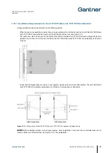
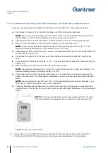
3.10.2 Installation Instructions for the GAT ECO.Side Lock 7010 F/ISO and Non-Metallic Doors
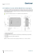
Complete the following steps to install the GAT ECO.Side Lock 7010 F/ISO into lockers with non-metallic doors.
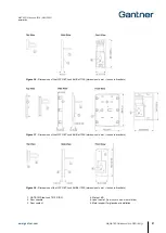
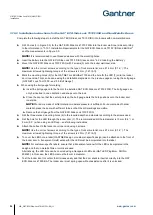
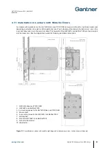
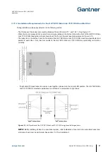
► Drill 3 holes (3 in Figure 3.9) for the GAT ECO.Side Lock 7010 F/ISO into the locker wall inner side according
to the information in "3.10.1. Installation Requirements for the GAT ECO.Side Lock 7010 F/ISO and Bolt Set"
and the measurements in Figure 3.9.
NOTE!
It is recommended to use threaded sleeves with the mounting holes.
► Insert the battery into the GAT ECO.Side Lock 7010 F/ISO (see section “4.2.2. Inserting the Battery”).
► Mount the GAT ECO.Side Lock 7010 F/ISO with 3 screws (3) onto the locker wall inner side.
NOTE!
Use the correct screws according to the type of locker material, max. Ø 4 mm (0.16´´). The
maximum allowed tightening torque of the screws is 2 Nm (1.47 lb-ft).
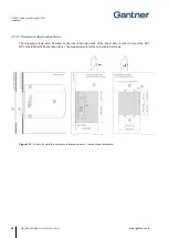
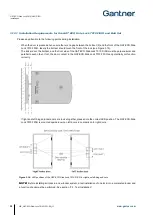
► Mark the mounting holes (6) for the GAT NET.Lock BoltSet 7100 and the hole for the LED (7) onto the locker
door inner side. This can be done using the installation diagrams on the previous pages or using the bolt gauge
(GAT NET.Lock Tool 7000 -
see “3.5 Bolt Gauge”).
► When using the bolt gauge for marking:
► Insert the bolt gauge onto the front of the installed GAT ECO.Side Lock 7010 F/ISO. The bolt gauge can
only be inserted in one orientation and snaps onto the lock.
► Close the door so that the center points on the bolt gauge mark the hole positions onto the locker door
inner side.
NOTE!
For doors made of softer material, moderate pressure is sufficient. For doors made of harder
material, press the door with sufficient force so that the drill markings are visible.
► Remove the bolt gauge from the GAT ECO.Side Lock 7010 F/ISO.
► Drill the three marked mounting holes (6) to the required depth and diameter according to the screws used.
► Drill the hole for the LED through the locker door (7). The recommended drill hole diameter is 10 mm (0.4´´) or
8 mm (0.3´´) when using an LED cap
– see following instructions.
► Attach the bolt set to the locker door inner side using 3 screws.
NOTE!
Use the correct screws according to the type of locker material, max. Ø 4 mm (0.16´´). The
maximum allowed tightening torque of the screws is 2 Nm (1.47 lb-ft).
► To cover the LED hole, a label (GANTNER design or customer-specific design) can be attached to the front of
the locker door. A transparent (matt) window for the LED must be incorporated into the label.
NOTE!
For customer-specific labels, ensure that a transparent window for the LED is incorporated in the
design and that no metallic films or colors are used.
Alternatively, the LED hole can be covered using a transparent LED cap (GAT LED Plug 8mm, Part No.
806325). In this case, the LED hole must be 8 mm in diameter.
► Test the locker door to confirm that it closes easily and that the door shackle inserts correctly into the GAT
ECO.Side Lock 7000 BA. The locker door must spring open without assistance after it is unlocked.
Summary of Contents for GAT ECO.Side Lock 7010 F/ISO
Page 63: ......

