14
INSTALLATION
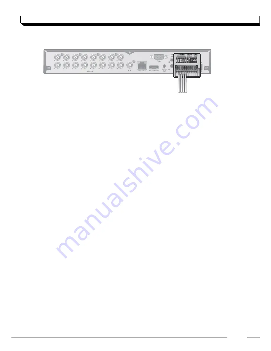
Alarm I/O Connection
To connect the alarm input signal
1. Push the Alarm In and
[GND]
terminal
s’ buttom side with a sharp tipped tool such
as screw driver.
2. While pushing, insert alarm signal cable into the hole of the Alarm In terminal.
3. While pushing, insert ground signal cable into the the hole of the
[GND]
terminal.
4. To check proper insertion of the cable, stop pushing and gently pull the cable and
Test whether it disconnects.
5. To disconnet the cable, push the button side the terminal and pull out the cable.
To connect the Relay output signal
1. Push the
[NO]/[NC]/ [COM]
terminals’ bottom side with a sharp tipped tool such as
screw driver.
2. While pushing, insert alarm signal cable into the desired terminal of
[NO]
or
[NC]
.
NO(Normal Open) : normally Open but switching to Close if an alarm out occurs.
COM : Insert the grounding wire.
NC(Normal Close) : Normally Close but switching to Open if an alarm out occurs.
3. Insert the ground signal wire into the hole of the
[COM]
port.
4. To check proper insertion of the cable, stop pushing and gently pull the cable and
Test whether it disconnects.
5. To disconnet the cable, push the button side the terminal and pull out the cable.
Summary of Contents for digimaster DR-4FX1
Page 1: ...1...


