background image

60

SEARCH

SEARCH

Press 

ENTER

to select the calendar and use the 

CURSOR KEYS

to move the purple square to the 

required day. 

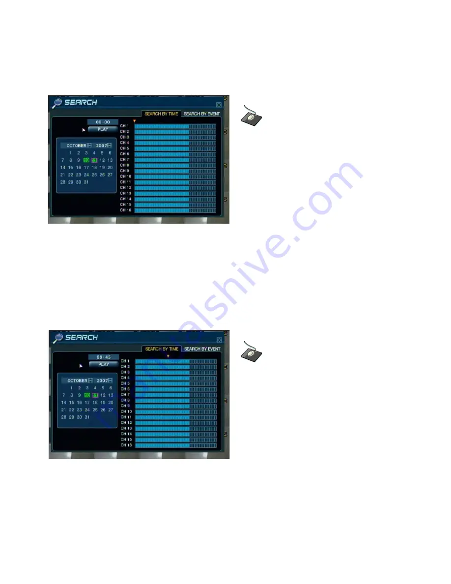
As different days are selected, the timeline display also changes to show recorded footage on that day.

Press 

ENTER

to choose the day and move over to the timeline.

Click and drag the yellow arrow along the timeline by 
clicking on the arrow and holding the left mouse 
button, while moving the mouse from right to left.

The position of the arrow will indicate the desired 
time from which to begin playback.

TIME SEARCH   

(continued)

Use the 

CURSOR KEYS 

to move the timeline arrow left or right to select a block of time from the timeline.

Each movement of the timeline arrow will increase or decrease the time in 15 minute increments. 

The currently selected time is displayed above the calendar.

Press 

ENTER 

to begin playback from the selected time.

Click the 

PLAY

button to begin playback from 

the selected Date and Time. 

Summary of Contents for DIGIMASTER DR4N

Page 1: ...1 ...

Page 2: ...a y 2 2 S Y S T E M S E T U P 2 1 L i v e D i s p l a y E d i t M o d e 1 6 D i v i s i o n S c r e e n 1 5 L i v e D i s p l a y C o n f i g u r e 1 5 F r o n t P a n e l D e s c r i p t i o n 4 c h 1 1 R e a r P a n e l D e s c r i p t i o n 4 c h 1 2 R e m o t e C o n t r o l l e r D e s c r i p t i o n 1 3 R e a r P a n e l D e s c r i p t i o n 8 1 6 c h 1 0 F r o n t P a n e l D e s c r i p ...

Page 3: ...u p 5 1 A r c h i v i n g 6 4 E v e n t S e a r c h 6 2 R e c o r d i n g o p e r a t i o n s 5 0 R E C O R D M E N U 5 0 C l i e n t S o f t w a r e I n s t a l l a t i o n 6 7 R e m o t e C l i e n t S e t u p 6 7 C l i e n t S o f t w a r e O r g a n i z a t i o n 6 9 D i s k M a n a g e 4 9 E v e n t S e n s o r 4 4 C o n t r o l D e v i c e 4 4 S y s t e m M a n a g e m e n t 4 3 A l a r m O ...

Page 4: ... 4 R e m o t e R e c o r d i n g S e t u p 8 1 E v e n t V i e w e r 8 0 S t i l l S h o t 7 8 L o g V i e w e r 7 9 B a c k u p P l a y e r 7 9 P r i n t 8 0 A r c h i v i n g 7 8 Q u i c k S e a r c h 7 7 E x p l a n a t i o n o f F u n c t i o n K e y s 7 6 R E M O T E S E A R C H 7 5 ...

Page 5: ...40 704x288 6 16 Kbyte 704x480 704x576 Image size 3 X HDD No limit in capacity Hard disk capacity USB default USB memory stick USB HDD ODD DVD CD RW option Secondary Storage 4 8 16 x TTL programmable as NC NO Alarm inputs 4 8 16 x TTL Alarm outputs For monitors with Multi Sync Function only 1024 X 768 60Hz VGA 5 secs Pre 3 mins Post programmable per camera Pre Post alarm recording Up to 16Channel s...

Page 6: ...e Dutch Portuguese French Russian Japanese Polish Romanian German OSD languages 10 100 Base TX RJ 45 Ethernet interface Live View Live Recording Search Set up Archiving Remote Function RS 485 interface PTZ Control 100VAC 240VAC 60 50Hz Supply voltage 5 to 50 Temperature range 4CH 3 8KGS 8 16CH 7 3KGS Weight 4CH 36cmX39cmX7cm 8 16CH 43cmX46cmX9cm Dimensions HxWxD Black Color ...

Page 7: ...the package Basic Contents Remote Controller Instruction Manual Remote Agent Installation CD AAA Battery x 2 AC Power Cable Optional Contents Internal Hard Disk Drive Internal CD RW Drive USB Thumb Drive DR8N or DR16N Unit DR4N 12V Adaptor Specifications Organization Specifications Organization ...

Page 8: ...ns Organization 3 System Organization NETWORK Camera 1 16 Alarm Sensor 1 16 Relay Out VCR VGA Monitor A V Monitor Remote Client PC Image Printer Video In Video Out TCP IP Alarm Input Out Remote Controller CD RW Backup AVI Backup WEB Client USB ...

Page 9: ...Present System Status POWER REC NETWORK Channel Selection Buttons 1 8 16 Select Channel or Input Password Directional Navigation Buttons UP DOWN LEFT RIGHT ENTER Remote Controller Input Sensor IR EJECT Eject CD DVD ROM Optional Focus Adjust Near Far or Reverse Play Rewind Ⅱ Pause Playback Iris Adjust Open Close or Forward Play Fast Forward JOG SHUTTLE Outer wheel variable REW or FF Inner wheel scr...

Page 10: ...dividually Sequenced Spot Monitors Audio In 4 x RCA Audio Line Input Terminal Audio Out RCA Audio Line Out Terminal Alarm 8 16 x Input TTL Alarm Sensor Input Terminal Relay 8 16 x Relay Output Terminal USB PORT USB Port for use of a USB Memory Stick and or USB HDD Backup VGA OUT VGA Main Monitor Output to a Computer Monitor RS 232C Serial Configuration Port for Program Debugging RS 485 Serial Inte...

Page 11: ... Off REC Record On Off ALARM Alarm Sensor Detection Status NET Client Network Connection Status Search Controller Searching Recorded Data or Control Menu PTZ FOCUS HOLD Hold Jog dial JOG dial Eject Eject CD DISPLAY Select Screen Division Mode or Rotation Mode SEARCH Go to Search Mode for Searching Data SETUP Go to System Menu PTZ FOCUS Go to Camera PTZ FOCUS Control RETURN Cancel Setup or Return t...

Page 12: ...a Video to Loop Back Port 4 BNC Port Monitor Out Output DVR Video to AV Monitor Spot Out Output Spot out Video to AV Monitor NTSC PAL Select NTSC or PAL Video Format VGA OUT Output Video to a VGA Monitor S Video Out Output Video to a S Video device Audio Out Output Audio Data Audio In Audio Input Terminal Related with 1 4 Camera Ethernet TCP IP RJ 45 Jack to connect DVR to Ethernet LAN for Remote ...

Page 13: ...Remote controller set each ID on DVR Can control all DVRs on one Remote controller by each ID Navigation Buttons Used for Playback Control Menu Navigation and PTZ Focus Control ID ID Button Select DVR ID How to set ID on the remote controller Press the ID button then displayed INPUT ID statement Press the set ID and Press the RETURN button The default ID is 01 For DVR ID see the page44 For returni...

Page 14: ...f hard drives and the CDRW DVR RW drive After startup diagnostics are complete the operator must logon to the system The default user name is ADMIN Using the CHANNEL SELECTION buttons key in the default password of 1234 and press the ENTER button The DVR begins normal operation and shows the default display of all 16 channels The status bar at the bottom of the screen shows current time and date a...

Page 15: ...equence modes All the display modes are static with the exception of the sequence mode In this mode the sequence symbol is displayed and each channel is shown in full screen for a set period of time default 3 sec before switching to the next channel The sequence runs indefinitely until a different display mode is chosen Click the right mouse button on the Live Display screen and Click SCR MODE Cli...

Page 16: ...VE DISPLAY EDIT MODE In this example the default 8 screen mode displays channels 1 8 To display channel 10 instead of channel 5 Using the CHANNEL SELECTION buttons press number 5 channel 5 will change to a blue screen Now you may press number 10 to put that channel in the place where channel 5 was Press Enter to confirm the change and exit Live Display Edit Mode or select another channel to edit L...

Page 17: ...igital Zoom operation can only be done within Live View Mode To adjust the zoom level turn the SHUTTLE WHEEL clockwise to increase zoom or counter clockwise to decrease zoom To move the zoom area around the image use the CURSOR KEYS to adjust the position of the zoom square Press the RETURN button to return to normal live display mode LIVE DISPLAY LIVE DISPLAY Click the right mouse button on the L...

Page 18: ...ll override all standard recording settings to provide by default continuous recording on all channels The Panic Recording settings can be edited within the Record Menu Press the PANIC button The top right of the display shows a red square only to indicate that the DVR is in panic recording mode Press the PANIC button again to return to normal Timer or Motion recording mode Click the right mouse b...

Page 19: ...k on the Password field and the Virtual Keyboard will appear Then enter the password and click the button PTZ Camera Control Speed domes and other telemetry devices connected to the DVR can be fully controlled from the front panel In live display mode press the PTZ button To select a camera to control use the CHANNEL SELECTION buttons Pan and tilt movement is controlled by the CURSOR KEYS zoom is ...

Page 20: ... ENTER to recall a pre programmed swing pattern Press RETURN to exit PTZ mode and return to live view LIVE DISPLAY LIVE DISPLAY PTZ Camera Control continued Click the SWING menu Click the GANZ menu to enter the PTZ internal OSD menu GANZ PTZ cameras only Use the directional buttons to navigate the OSD Press ENTER to confirm a selection Press RETURN to exit the OSD menu control ...

Page 21: ...uttons In general the ENTER button is used to select and change a particular item and the RETURN button is used to cancel a change or exit from a particular setup screen To setup all main system functions highlight SYSTEM SETUP and press ENTER SYSTEM SETUP SYSTEM SETUP Right Click the mouse in Live Display Mode Left Click the SETUP menu Double click on the Password field and the Virtual Keyboard w...

Page 22: ...se motion recording is occurring the operator can use this feature to determine and rectify the cause in realtime OFF normal display mode ACTIVE areas where motion is detected are highlighted with colored blocks INACTIVE areas where no motion is detected are highlighted with colored blocks MOTION COLOR The color of the blocks displayed when MOTION SENSOR DISPLAY is set to ACTIVE or INACTIVE MOTION...

Page 23: ...tion will cause the associated channel to display full screen MOTION POP UP DWELL Determines how long the full screen popup is displayed after motion detection If motion continues the popup screen is displayed constantly DISPLAY MODE The DVR output can be optimized for display on a VGA or AV CRT monitor To change any of these settings highlight MONITOR and press ENTER to select Use the CURSOR KEYS...

Page 24: ...m sequence using mixed multi screen views and any desired channels To add a new sequence highlight ADD and press ENTER Sequence title is highlighted press ENTER to bring up the virtual keyboard Use the virtual keyboard to type in a name or reference number for the new sequence SYSTEM SETUP SYSTEM SETUP Click the SEQUENCE menu Click the ADD menu to set up a new sequence ...

Page 25: ...To use CAPS and access symbols use To exit use SYSTEM SETUP SYSTEM SETUP Double click on the SEQUENCE TITLE field The Virtual Keyboard will appear Enter the title and click the button to confirm In order to activate the newly created sequence set ACTIVATION to ON highlight SAVE and press ENTER to display the sequence programming screen Click on the ACTIVATION field and use the button to toggle ON ...

Page 26: ... displayed use the CHANNEL SELECTION buttons to enter the channels into each section of the multi screen modes Note Only one instance of each channel can be displayed To remove a channel press the appropriate CHANNEL SELECTION button again SYSTEM SETUP SYSTEM SETUP Double click on the first screen of the sequence and the box will be outlined in yellow Each time the screen is clicked the display mo...

Page 27: ...equence To finish editing the sequence press RETURN and then select save and exit Press ENTER SYSTEM SETUP SYSTEM SETUP When you have finished selecting each of the channels Left click on the screen and the next sequence screen will appear Select the display mode the select the channels to use in the multi screen To finish adding sequence screens right click on the screen Click the SAVE EXIT menu ...

Page 28: ...hannel DVR has 4 SPOT MONITOR OUTPUTS Each one displays a full screen sequence of channels depending on the settings configured in this menu For each spot monitor the operator can decide which channels are displayed For example Spot Monitor 1 could display channels 1 4 Spot 2 could display channels 5 8 and so on Left click on the SPOT OUT menu tab Click the checkbox to toggle the channels ON OFF w...

Page 29: ... Spot Output Ch 1 4 Use the CURSOR KEYS and ENTER button to check or uncheck the channels to include in the sequence After the changes have been made highlight APPLY and press ENTER to save SYSTEM SETUP SYSTEM SETUP Click on the checkbox for each desired channel to toggle that channel ON OFF for spot output ...

Page 30: ...ded TITLE For each camera a title of up to 11 characters can be set using the Virtual Keyboard SYSTEM SETUP SYSTEM SETUP Click the CAMERA menu Click the CAMERA TITLE menu You may switch the COVERT setting ON OFF for each channel on the system Click the button to toggle the setting ON OFF Double click the TITLE field for a particular channel to edit the channel title using the Virtual Keyboard ...

Page 31: ...h channel to modify and press ENTER Click the COLOR SETUP menu Click on the values for BRIGHTNESS CONTRAST TINT and COLOR to modify them The selected channel will be displayed in full screen BRIGHTNESS CONTRAST TINT and COLOUR can be changed as necessary To modify a different channel highlight the CAMERA field and choose the desired channel Press RETURN when all changes are complete DISPLAY COLOR ...

Page 32: ...justed for each channel by selecting the icon and pressing ENTER Note that some settings such as AUTO FOCUS may not be compatible with particular PTZ equipment If this is the case changing this value will have no effect on PTZ control Click the PTZ SETUP menu Click on each value within the ADDRESS PROTOCOL and BAUD RATE menu Change the value by button Click the button to change the PTZ details by ...

Page 33: ...llows the operator to define which areas of the image are monitored for motion detection Light blue grid squares represent detection areas grey grid squares are ignored The sample image above shows that motion will be detected across the entire image SYSTEM SETUP SYSTEM SETUP Click the MOTION SENSOR menu Click the value on the SENSITIVITY menu Change the value by button Click the button to edit th...

Page 34: ... the green cursor square in the top left of the display Move the cursor using the CURSOR KEYS to the first corner of the area to be set and press ENTER the cursor turns yellow To select or deselect the entire grid at one time right click on the grid and click SELECT ALL or DESELECT ALL Left click and drag the cursor across the motion area grid while holding the left mouse button This action will o...

Page 35: ...o mask off or include other areas of the image Once the detection area has been defined press RETURN and choose SAVE EXIT to save the area and return to the motion setup menu To exit without saving choose CANCEL NOTE The motion recording schedule must be defined within the RECORD MENU as described on page 52 Without setting the schedule the DVR system will use Timer Continuous Recording Click the ...

Page 36: ...O MONITORING CHANNEL Specifies which one of the 4 AUDIO INPUTS is routed to the AUDIO OUTPUT while in multi screen mode NETWORK AUDIO TX When set to ON live and playback audio is transmitted to a remote PC connection NETWORK AUDIO RX When set to ON allows a remote PC connection to send audio back to the DVR Click the SOUND menu Click the AUDIO menu Click on a field to edit Then click the button to...

Page 37: ...R REMOTE When set to ON each button press on the IR Remote Control is confirmed by a beep SYSTEM SETUP SYSTEM SETUP SYSTEM To setup the various system options highlight SYSTEM and press ENTER Click the BUZZER menu Click on a field to edit Click the button to toggle ON OFF Click the SYSTEM menu ...

Page 38: ... Internet the time and date can be set automatically by selecting SYNC and by pressing ENTER TIME ZONE SETUP This should be set according to the region that the DVR is used in D S T When set to ON the DVR will automatically adjust the Daylight Savings Time by one hour on the relevant date in the spring and autumn DATE TIME Click the DATE TIME menu Click on a field to edit Click the button to toggl...

Page 39: ...d the subnet mask can be manually set by the user 1ST DNS SERVER If DHCP is not being used the first DNS server can be manually set by the user 2ND DNS SERVER If DHCP is not being used the second DNS server can be manually set by the user DDNS SERVER If DDNS is enabled the host DDNS server is specified here NET CLIENT PORT The port number that the DVR uses to support remote connections from the cl...

Page 40: ...to this menu in order for the mail function to work properly The username cannot contain spaces SYSTEM USER MANAGEMENT By default the DVR is configured with a user ID of ADMIN which belongs to the ADMIN user group and has an initial password of 1234 As well as the ability to add new users existing user details can be modified To modify user details highlight the user with the green cursor and pres...

Page 41: ...AIL Enter the users e mail address if e mail notification is required E MAIL NOTIFICATION Enable or disable e mail notifications for this particular user NOTE It is recommended that the initial ADMIN password by changed as soon as possible to protect the DVR system from any unauthorized access SYSTEM SETUP SYSTEM SETUP SYSTEM USER MANAGEMENT continued Double click the ADMIN on the GROUP menu to ed...

Page 42: ... USER ID and PASSWORD by double clicking the field and using the Virtual Keyboard Use the button to confirm the new settings Only the permissions of the MANAGER and USER account types can be configured ADMIN accounts will always have all permissions granted by default To check or uncheck a permission move the cursor over a checkbox and click the ENTER button Click the PRESS button next to the Auth...

Page 43: ...ication e mails can be identified more easily between multiple DVR systems PASSWORD This setting toggles the system password prompt ON or OFF F W UPDATE Firmware updates may be released periodically to enhance system performance and add extra features The operator can upgrade the firmware using a USB Memory Stick FACTORY DEFAULT If settings have been changed which cause erratic behavior in the DVR...

Page 44: ...VR must have unique ID for control by Remote controller PROTOCOL This is the driver set that is used for an external Serial controller BAUD RATE This value should be set to match the baud rate of the PTZ controller SYSTEM SETUP SYSTEM SETUP EVENT SENSOR To setup the various event handling options highlight EVENT SENSOR and press ENTER Click the EVENT SENSOR menu Click the CONTROL DEVICE menu Selec...

Page 45: ...These settings will determine the behavior of each of the 16 alarm inputs OPERATION Alarm inputs can be enabled or disabled with this option TYPE Alarm inputs can be set as normally open N O or normally closed N C SYSTEM SETUP SYSTEM SETUP Click the HDD EVENT menu You may click on the DRIVE SMART ALARM and CHECK INTERVAL values to change these settings You may edit these settings by using the butt...

Page 46: ...h 0V to 5V when activated or active low 5V to 0V when activated HDD EVENT Determines whether a hard drive event will trigger the selected alarm relay output Action settings ALARM Determines whether any selected alarm inputs will trigger the alarm output VIDEO LOSS Determines whether video loss on any of the selected channels will trigger the alarm output MOTION Determines whether motion detection ...

Page 47: ...zer sounds after it has been triggered HDD EVENT Determines whether a hard drive event will activate the buzzer Action settings ALARM Determines whether any selected alarm inputs will sound the buzzer VIDEO LOSS Determines whether video loss on any of the selected channels will sound the buzzer MOTION Determines whether motion detection on any of the selected channels will sound the buzzer NOTE Re...

Page 48: ... alarm inputs will send an e mail notification VIDEO LOSS Determines whether video loss on any of the selected channels will send an e mail MOTION Determines whether motion detection on any of the selected channels will send an e mail NOTE There are some other E mail settings that must also be configured These are found within the MAIL and USER MANAGEMENT menus as described on page 41 SYSTEM SETUP...

Page 49: ...ys be 99 When set to OFF the DVR will stop recording when the disk becomes full FORMAT If necessary all footage can be erased permanently from the DVR by using this option NOTE When the RECORD TIME LIMIT is set the percentage of HDD used shown in live display mode may never reach 99 For example suppose that the total HDD capacity of the DVR allows for a recording time of 4 days under normal condit...

Page 50: ... this setting determines the amount of footage that is always recorded before an event occurs motion detection alarm input etc POST EVENT RECORDING TIME When the DVR is not in continuous recording mode this setting determines the amount of footage that is always recorded after an event occurs motion detection alarm input etc RECORD MENU RECORD MENU Right click within Live View Mode and select SETU...

Page 51: ...e that when SCHEDULE MODE is set to WEEKLY each day of the week can also be selected SCHEDULE This section determines at what times the DVR will record and whether it is continuous recording or motion based recording RECORD MENU RECORD MENU Click the TIMER MOTION SETUP menu PARAMETER To change the PARAMETER settings highlight TIMER MOTION SETUP and press ENTER Check to see that the word PARAMETER ...

Page 52: ... 09 00 position and press ENTER The cursor changes to yellow to show the start position Use the CURSOR KEYS to stretch the yellow selection area across to the 18 00 position RECORD MENU RECORD MENU PARAMETER continued Click on the TIMEBAR You may use the mouse to select a one hour block of time by clicking on the desired block Click and drag the mouse along the timebar to select several one hour b...

Page 53: ...LITY Four different picture recording qualities can be set for each channel from Highest to Low AUDIO If any audio inputs are connected to the DVR each of the four audio channels can be assigned to any of the video channels A single audio source channel can be assigned to multiple video channels NOTE The default settings for all channels is 352 x 240 at 7FPS and at the HIGHEST quality level NOTE T...

Page 54: ...or on the upper left block on the schedule grid Example To set all channels to motion detection recording only between 18 00 and 00 00 Use the CURSOR KEYS to move the green cursor to the 18 00 position and press ENTER The cursor changes to yellow to show the start position RECORD MENU RECORD MENU Click on the SCHEDULE menu tab Click on the schedule grid Select the Time and Channel to set the sched...

Page 55: ...ENU Click and Drag to select an area of the grid This area will represent the channels and time range that you will set the schedule properties for Press ENTER select a recording mode setting and press ENTER again NONE no recording TIMER continuous recording MOTION motion based recording After you have selected an area on the grid with your mouse choose a recording mode setting ...

Page 56: ...e above procedure to set different recording schedules for individual channels and time periods NOTE The schedule grid uses 3 symbols to show the different recording modes DARK BLUE blocks No recording LIGHT BLUE blocks Continuous recording DARK BLUE block with a LIGHT BLUE center Motion based recording RECORD MENU RECORD MENU ...

Page 57: ...s at what times the DVR will record and whether it is continuous recording or motion based recording NOTE Please refer to the Timer Motion setup procedures page 51 for details on how to configure the PARAMETER and SCHEDULE menus NOTE Alarm activated recording can be used in conjunction with Timer Motion recording For example the DVR could be configured to record continuously at a low frame rate se...

Page 58: ...other recording settings and record continuously on all channels using the settings configured within this menu RECORD MENU RECORD MENU Click on the PANIC SETUP menu This menu is configured in a similar way to the PARAMETER portion of the Timer Motion Setup or Alarm Setup menus ...

Page 59: ...ses a calendar and timeline search method for quick access to recorded footage The calendar displayed on the left shows the current month Days highlighted in green have recorded footage The timeline on the right shows a 24 hour status of all channels for the selected day Each block on the timeline represents 15 minutes of time Light blue areas show recorded footage Right click within Live View Mod...

Page 60: ... holding the left mouse button while moving the mouse from right to left The position of the arrow will indicate the desired time from which to begin playback TIME SEARCH continued Use the CURSOR KEYS to move the timeline arrow left or right to select a block of time from the timeline Each movement of the timeline arrow will increase or decrease the time in 15 minute increments The currently selec...

Page 61: ...e another time and date press RETURN To exit the search screen and go back to live view repeatedly press RETURN Turning the SHUTTLE WHEEL counter clockwise will reverse playback by up to 64x When the SHUTTLE WHEEL is released playback will be paused If the HOLD button is pressed and released during SHUTTLE WHEEL operation the last shuttle function is held even if the wheel is released When playbac...

Page 62: ... the number of events displayed in the search Using the CURSOR KEYS and the ENTER button select the FROM and TO date time and the types of events and channels to search Right click within Live View Mode Select the SEARCH menu Double click on the Password field and the Virtual Keyboard will appear Then enter the password and click the button Click on the SEARCH BY EVENT menu Click on the FROM and T...

Page 63: ...OG WHEEL and play control buttons can be used as normal To stop playback and return to Live View mode repeatedly press RETURN NOTE The event search contains the following selectable entries Use the checkbox to include ALARM When checked all alarm input events are displayed for the chosen date range TIMER When checked scheduled recording operations are displayed for the chosen date range MOTION Whe...

Page 64: ...hich device to send it to Use the CURSOR KEYS to navigate around the Archiving screen To change any value or setting press ENTER to change the green cursor to yellow Use the up and down CURSOR KEYS to change the value Press ENTER to accept the value or RETURN to cancel To change a checkbox setting press ENTER to check or uncheck the box ARCHIVING ARCHIVING Right click within Live View Mode Select ...

Page 65: ...ed in the archive Once all the desired archive options have been selected highlight the START button and press ENTER The DVR displays a list showing the information to be archived and the total archive size If the ORIGINAL SIZE is larger than the available space on the backup media the END TIME of the archive set is reduced until the clip will fit on the media The MODIFIED SIZE is the final file s...

Page 66: ...tracted the footage is copied to the CD DVD disc or USB Memory Stick NOTE Depending on the amount of footage selected for archive the extracting and burning process may take some time during which the DVR cannot be operated from the Front Panel or Handheld IR Remote Normal recording is unaffected by the archive process ARCHIVING ARCHIVING ...

Page 67: ...emote playback remote configuration bi directional audio support remote archiving and remote alarm triggering can all be achieved using the client software REMOTE CLIENT SETUP REMOTE CLIENT SETUP Client Software Installation Insert the CD that is supplied with the DVR into your PC s CD ROM drive The install process will begin automatically and display the following screen Click Next to continue Cl...

Page 68: ...llation was successful Two icons will be created on the PC desktop Remote Agent is the main software package BackupPlayer is the software to view archived footage from the DVR To begin using the remote client software double click the icon on the desktop or click Start Programs Remote Agent DVR Remote Agent The main remote client window is displayed ...

Page 69: ...o access remote playback menu SETUP button to configure local connection settings DVR SETUP button to adjust DVR settings remotely DROP DOWN LIST to select a DVR connection group CONNECT button DISCONNECT button DISPLAY button to choose 1 4 9 or 16 screen display SEQUENCE button MANUAL SWITCH button FULL SCREEN button SAVE TO AVI button EVENT VIEWER button PTZ CONTROL buttons ...

Page 70: ...s DVR SETUP Button Remote Setup of the currently connected DVR requires ADMIN level access DROP DOWN LIST Select the DVR group to connect to CONNECT Button Connect to the DVR group DISCONNECT Button Disconnect from the DVR group DISPLAY Button Change the screen division mode to 1 4 9 or 16 channel view SEQUENCE Button Change automatically from one channel to the next in a single channel view mode ...

Page 71: ...reate a connection group click the SETUP button to display the Local Configuration screen In the Group window on the left right click on Site and choose Add Group Choose a name to easily identify the connection group and click OK to create the new group Example The group name is OFFICE The new group is created Click on the name of the newly created group and the DVR Information blanks on the right...

Page 72: ...ed to the remote client display channels The client window will show up to 16 channels of video in a 4x4 grid display Using the drop down lists under the DVR section select which channels are displayed and in what position To ignore certain channels leave the drop down marked with an x In this case only channels 1 4 from the selected DVR will be displayed NOTE Only one instance of each channel of ...

Page 73: ...are in live view mode In Connection retries choose the number of times the remote client will attempt to re connect on a failure When you have completed the configuration of all DVR properties click ADD to save all the details To add up to three more DVR systems into this group simply repeat the steps from the previous page in the Enter DVR details section To create another connection group repeat...

Page 74: ...est results leave set at the default setting of Video Renderer Overlay mixer and GDI are provided only for backwards compatibility with older PCs Video Mode Define the sequence time between each channel when the software is in sequence mode Also determines the full screen popup time when an alarm is triggered on the DVR Video Display For best results leave Quality improve selected Saving directory...

Page 75: ...SETUP REMOTE CLIENT SETUP LIVE VIEW MODE button DVR SETUP button LOCAL SETUP button DISPLAY MODE buttons ARCHIVING button SAVE IMAGE button EVENT LOG VIEWER button BACKUP PLAYER button PRINT IMAGE button EVENT VIEWER button CAMERA SELECTION buttons SEARCH BY DATE TIME SEARCH CONTROLLER buttons SEARCH TIMELINE BAR ...

Page 76: ... still image in either BMP or JPG format EVENT LOG VIEWER Button Can see all BACKUP PLAYER button Execute the backup player program PRINT IMAGE Button Send the current playback still image to the printer EVENT VIEWER Button View all events that have occurred since the start of the remote connection CAMERA SELECTION Buttons Select a camera by channel number SEARCH BY DATE TIME Select a date and tim...

Page 77: ...sting the date value using the arrow keys As different dates are selected the SEARCH TIMELINE will change to show the recorded footage for the selected date Use the mouse to drag the TIME BAR to the desired time The exact time selected will be displayed under the date Click to begin playback from the selected date and time To change the play direction to reverse play click Use the and buttons to i...

Page 78: ...lude audio if applicable Choose Select All to highlight all available channels including audio to add to the archive Click OK to begin downloading the archive data to the PC hard drive During playback a still image can be saved to the local PC hard disk by clicking the SAVE IMAGE button Specify the file location and filename and choose BMP or JPG format Click Save to save the image The snapshot im...

Page 79: ...ols under the display can be used to adjust playback direction and speed To search for an event and playback the recorded footage press the EVENT LOG VIEWER button Choose the Start time and End time Select which types of events to include in the search and click Search The system event log for the selected time period is displayed in the search window Select an event click Go to timeline and then ...

Page 80: ...button Select the printer properties and click OK to print The printed image will appear exactly as shown on screen This includes the currently selected screen display mode While you are connected to a DVR any system events that occur during the duration of the remote connection are sent to the remote client event list To display this list click the EVENT VIEWER button ...

Page 81: ...b Recording Operations Schedule Mode Select Weekly or Daily Pre Event Recording Time Records an event and includes the buffer time before the event happened 0 5 seconds Post Event Recording Time Records an event and included the buffer time after the event happened 5 180 seconds Alarm Recording Schedule Click the SET Button to set the Alarm Recording parameters Set the image size image rate qualit...

Page 82: ...t the PTZ camera address protocol baud rate and other PTZ device properties Motion Area Select a motion sensitive area on one or more channels using a grid overlay with motion targets SOUND tab Live Audio Setup Live Audio Set to ON OFF Audio Monitoring Channel Select audio channel to hear when in multi channel viewing mode Network Audio TX Toggle network audio transmission DVR to client Network Au...

Page 83: ...s pushed on the DVR Buzzer Output Select the conditions that will activate the system buzzer Alarm Video loss Motion Buzzer Enable or disable the system buzzer Duration Set the buzzer time duration 5 seconds to 5 minutes or until a key is pushed on the DVR Disk Event Enable or disable buzzer activation based on detection of an HDD error Keypad Enable or disable buzzer chirp based on a Front Panel ...

Page 84: ...uding user ID and password optional to use the DVR e mail notification feature Users Add modify or delete a DVR user account Network Speed Select the maximum allowed DVR network speed Disk Overwrite Select ON OFF to overwrite older recording data on the HDD with newer data once the HDD is full Record Time Limit Select the time period for recorded data to remain on the HDD before being deleted by t...

Page 85: ...85 ...

Page 86: ...86 ...

Reviews: