EG-6
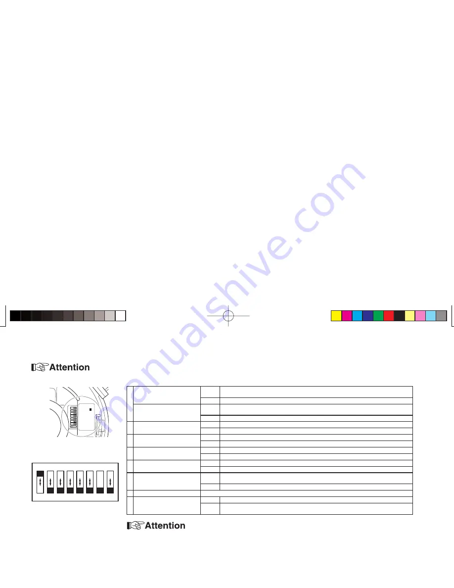
Setting the mode setting switch
Do not alter the position of the mode setting switch marked “FIX” from its factory default setting. If the set position is changed, the auto iris may
become inoperable.
$.$.
&)8
!'#(,
",#/./&&
&,/./&&
,,).4
7"!7"!47
$././&&
$.7"3YNC&,",#!'#&)8
/.!7",,/./.($.
/&&!47).4/&&/&&,$.
1
Digital Day/Night model:
ZC-D7312NHA
ON
Enables the automatic Day/Night switching. (Low light conditions: B/W, Normal light: color)
The digital processing provides high sensitivity pictures.
OFF
Color images only.
Mechanical Day/Night model:
ZC-DN7312NHA
ON
Enables the automatic Day/Night switching. (Low light conditions: B/W, Normal light: color)
The IR cut fi lter automatic switching provides high sensitivity pictures.
OFF
Color images only.
2
White Balance (WB)
AWB
Locks the white balance setting.
ATW
Adjusts white balance according to the color temperature of light source.
3
Synchronization (Sync)
INT.
Internal synchronization mode
L.L.
Line lock mode (24V AC, 60Hz only)
4
Flickerless (FL)
ON
Shutter speed to be fi xed at 1/100.
OFF
Normal position
5
Backlight compensation (BLC)
ON
Set to this position when a strong light is in the back ground.
OFF
Normal position
6
Auto Gain Control (AGC)
H
Adjusts brightness by a high sensitivity gain in low lighting conditions. The sensitivity is higher than
in the “L” setting.
L
Adjusts brightness by a standard gain in low lighting conditions.
7
FIX
Do not change the switch position from the factory setting.
8
Day/Night sensitivity switching
DN1
Standard brightness setting to activate the automatic Day/Night switching.
DN2
Brightness setting to activate the automatic Day/Night switching in lower lighting condition than in
DN1.
Setting the fl ickerless function to “ON” will give a darker picture than when set to “OFF” in low light conditions.
Factory default switch settings
Mode setting switch
(US)ZC-D7312NTSC.indd 6
(US)ZC-D7312NTSC.indd 6
2009/04/09 14:08:45
2009/04/09 14:08:45
Summary of Contents for ZC-D7000 SERIES
Page 1: ......


