background image

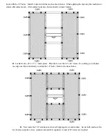
beam with the 1/8” holes.


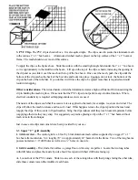
Install 14 clips to hold the mesh as shown below.  When applying the clips keep the mesh taut to

obtain a flat surface mesh.  A flat surface looks nice, but electrically it doesn’t matter

B.  

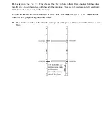
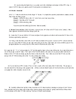
Locate the two 24” x 23 ½ ” mesh pieces.  Place them  over the 24” x 24” frame.  In so doing you will place

one edge over the mesh already covering the 1/8” holes.  Refer to the figure below.


D.  

Now locate the 5/16” stainless steel hex self-tapping screws and washers.  Secure both meshes to the

box beams, using the screws, washers and nut driver supplied.  A total of 20 screws are required.

Summary of Contents for SUPER C

Page 1: ...GAP SUPER C ANTENNA Installation and Assembly Instructions GAP Antenna Products Inc 99 North Willow St Fellsmere FL 32948 561 571 9922 WEBSITE http www gapantenna com...

Page 2: ...with power lines DO NOT TOUCH IT OR ATTEMPT TO MOVE IT IMMEDIATELY CALL THE POWER COMPANY 6 In the event of an accident involving power wiring DO NOT TOUCH THE VICTIM DIRECTLY Send someone for help 7...

Page 3: ......

Page 4: ......

Page 5: ...eir antennas Unlike all linear antennas the Super C is virtually independent of nearby metal objects in so far as detuning of the antenna is concerned However it is not wise to place a Super C next to...

Page 6: ...ice to use requiring no screws bolts or adhesives The corner is composed of two interrelated sections a clamping section and an insert section identified as a prong PVC corners are used to form the Su...

Page 7: ...rical conductivity is required self tapping stainless screws are used The nature of the clips is such that if excessive force is applied to the mesh for example ice snow and wind The clips will allow...

Page 8: ...These are to be used as a guide for establishing final placement of the corners see the next page C Slide the nearest corners to meet the end of the 22 tube Now locate the 21 9 16 1 x 1 tubes and slid...

Page 9: ...ube Slide all four prongs into the open ends of 1 x 1 tubes at the same time and snug Make sure all corners are properly positioned H A support bracket is required to interface the control grid and th...

Page 10: ...it doesn t matter B Locate the two 24 x 23 mesh pieces Place them over the 24 x 24 frame In so doing you will place one edge over the mesh already covering the 1 8 holes Refer to the figure below D No...

Page 11: ...set one edge of the prong next to the center mark just created with the pencil The prongs should face in or away from the screw holes on the other side of the tube 3 Locate the 26 1 x 1 tube and attac...

Page 12: ...s make sure your U bolts are facing the same direction now slide these assemblies together and snug all four tubes 11 Invert the rigid basket frame such that the screw holes on the bottom of the box a...

Page 13: ...h the aluminum mast with the hose clamp This will not happen if the mesh is placed so it just covers the frame 5 Twenty screws attach the two 12 x 26 mesh sections to the frame and complete the mechan...

Page 14: ...ve provided you with one After securing this mast simply place the bottom end of your open PVC tube with the rivets over this supplied 1 mast Nothing else is required As mentioned before you can set t...

Page 15: ...d 12 volts dc is being supplied Band selection is simple simply rotate the band selector switch on the switch box to the band you wish to operate When the led on the front panel lights 12 vdc is avail...

Page 16: ...our transceiver 5 Using an antenna tuner when the vswr is less than 2 1 is permitted Remember an antenna tuner does not tune the antenna but stops the reflected R F from reaching the transmitter and c...

Page 17: ...eturn This warranty is provided in lieu of any other warranty expressed or implied The warranty is void if the product is subject to misuse improper installation accident neglect modification repairs...

Reviews: