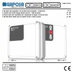
background image

230Vac /50Hz

QC

zero

QC

zero

P

p. 4

p. 18

p. 32

p. 46

Centrale di comando con ricevitore integrato - Istruzioni

Control unit with integrated receiver - Instructions

Armoire de commande avec récepteur integré - Instructions

Central de mando con receptor radio - Istrucciones

QCzero QCze

roP

Summary of Contents for QCzero

Page 1: ...p 32 p 46 Centrale di comando con ricevitore integrato Istruzioni Control unit with integrated receiver Instructions Armoire de commande avec r cepteur integr Instructions Central de mando con recepto...

Page 2: ...supply is cut off TURN THE MAIN SWITCH OFF before any other operation Queste istruzioni contengono delle importanti informazioni sull istallazione e l uso della centrale QC0 QC0P Conservatele sempre...

Page 3: ...ranchements doivent tre effectu s seulement une fois l alimentation principale d connect e COUPER l interrupteur G N RAL avant toute op ration Estas instrucciones contienen importantes informaciones s...

Page 4: ...PER COMANDO A 3 TASTI 3 4 1 PROGRAMMAZIONE TASTO APRI 3 4 2 PROGRAMMAZIONE TASTO CHIUDI 3 4 3 PROGRAMMAZIONE TASTO STOP 3 5 PROGRAMMAZIONE CODICI LAMPADA DI CORTESIA 3 6 CANCELLAZIONE TRASMETTITORI D...

Page 5: ...con ricevitore radio 1 UP PH TEST LIGHT ANT ON ED ST SS DW 2 3 4 5 6 7 8 9 10 11 12 13 14 15 16 17 18 19 20 21 22 23 1 ON 2 3 4 5 6 7 8 9 10 M UP START STOP EDGE COM COM COM FLASH DOWN STOP PHOTO MAX...

Page 6: ...ti 8 9 1 2 3 4 5 6 7 8 9 10 12 13 14 15 M 16 17 18 19 20 21 UP START STOP EDGE COM COM COM FLASH DOWN STOP PHOTO MAX 40 W TEST 24 Vac AUX 230 V 230Vac 50 60Hz C L N 11 MORSETTO DESCRIZIONE MORSETTO DE...

Page 7: ...ti dell alimentazione 24 Vac 10 11 e dei contatti 7 8 e 9 devono essere completamente separati 1 2 1 FOTOCELLULE TRADIZIONALI CON CONTATTO NORMALMENTE CHIUSO PULSANTE FUNZIONE MORSETTI DI COLLEGAMENTO...

Page 8: ...rsi al manuale delle fotocellu le utilizzate L alimentazione delle fotocellule riceventi separata da quella delle trasmittenti e va prelevata all uscita 24Vac della centrale Non necessario rispettare...

Page 9: ...in OFF Come comando di accensione di impianti di illuminazione ad ogni apertura se il dip 5 della scheda in ON L uscita del contatto ai morsetti 13 e 14 AUX ATTENZIONE Si pu collegare al massimo un ca...

Page 10: ...entrale pu essere comandata via radio permettendo la memorizzazione di 63 codici radio PROGRAMMAZIONE TRASMETTITORI Quando si programmano occorre mantenerli ad una distanza di almeno 50 cm dalla centr...

Page 11: ...p 7 in ON i dip 9 e 10 devono stare in OFF 2 Inviare il codice radio da memorizzare 3 Il led TEST esegue 1 lampeggio se il codice stato memorizzato 3 lampeggi se gi presente in memoria Quando la memor...

Page 12: ...mente importante verificare il verso del motore e la posizione dei finecorsa Se le fasi del motore sono invertite anche i sistemi di sicurezza hanno di un funzionamento invertito creando una situazion...

Page 13: ...i di sicurezza viene fermato il movimento del motore 2 Posizionare la porta a met corsa Mettere i dip 1 e 2 in OFF e poi il dip 6 in ON 3 Dare un comando SS 1 la porta inizier ad aprirsi Quando arriva...

Page 14: ...a fotocellula inverte il movimento della porta in apertura FUNZ IN CHIUSURA ED IN APERTURA mettere il dip 3 in ON durante la chiusura l intervento della fotocellula inverte il movimento della porta Du...

Page 15: ...te resistive con contatto da 8K2 4 5 LOGICA LAMPADA DI CORTESIA Il contatto della lampada di cortesia pu avere 2 modi di funzionamento OPERAZIONI 1 Posizionare in ON il dip 6 della centrale 2 Commutar...

Page 16: ...Indica lo stato dell ingresso CHIUDI mors 2 3 SS Indica lo stato dell ingresso Start Stop mors 4 5 ST Indica lo stato dell ingresso STOP mors 5 6 ED Indica lo stato della COSTA mors 7 8 Quando la cos...

Page 17: ...usibile Fuse2 Sono rimasti in ON i dip 6 7 8 9 o 10 Posizionare in OFF i dip 6 7 8 9 10 La porta si muove solo in apertura La fotocellula F1 guasta o occupata il led F1 spento Verificare lo stato dell...

Page 18: ...G OF THE OPEN BUTTON 3 4 2 PROGRAMMING OF THE CLOSE BUTTON 3 4 3 PROGRAMMING OF THE STOP BUTTON 3 5 PROGRAMMING OF THE COURTESY LIGHT CODE 3 6 REMOVE TRANSMITTERS FROM THE MEMORY 3 7 PROGRAMMING WORKI...

Page 19: ...ntegrated receiver 1 UP PH TEST LIGHT ANT ON ED ST SS DW 2 3 4 5 6 7 8 9 10 11 12 13 14 15 16 17 18 19 20 21 22 23 1 ON 2 3 4 5 6 7 8 9 10 M UP START STOP EDGE COM COM COM FLASH DOWN STOP PHOTO MAX 40...

Page 20: ...18 19 20 21 UP START STOP EDGE COM COM COM FLASH DOWN STOP PHOTO MAX 40 W TEST 24 Vac AUX 230 V 230Vac 50 60Hz C L N 11 CONNEC TION TERMINALS DESCRIPTION CONNEC TION TERMINALS DESCRIPTION 1 UP N O 10...

Page 21: ...e completely separated 1 2 1 SAFETY BEAMS with normally closed contact PUSHBUTTONS FUNCTION CONNECTION TERMINALS UP Normally open Shutter s opening Must be linked to terminals 1 up and 2 com DOWN Norm...

Page 22: ...e termi nals 10 and 12 TEST POWER SUPPLY RECEIVERS refer to the instructions booklet of the safety beams in use The power supply of the receivers safety beam is separated by that of the receiving one...

Page 23: ...gnition control for lighting systems at every opening when the board s dip 5 is in ON position The contact s output is at the terminals 13 and 14 AUX ATTENTION Max loading capacity is 5A at 230 Vac 2...

Page 24: ...QCTSE2 QCTSE4 The control unit can be controlled via radio and 63 radio codes can be memorized TRANSMITTERS PROGRAMMING When programming the transmitters it is necessary to keep them at a 50 cm dista...

Page 25: ...on dip 9 and 10 must remain in OFF position 2 Send the radio code to be memorized 3 The TEST led makes 1 flash if code has been memorized or it flashes 3 times if already memorized previously when mem...

Page 26: ...solutely important to verify the motor s direction and the limit switch position If the motor s lines are inverted the safety devices will have an inverted activity as well creating in this way a DANG...

Page 27: ...safety devices then the motor stops 2 Place the door at half way Place the dip 1 and 2 in OFF position and then dip 6 in ON position 3 Give a START STOP SS signal the door starts to open When opening...

Page 28: ...ts the movement of the opening door FUNCTION DURING CLOSURE AND OPENING place the dip 3 in ON position while closing the safety beam s activity inverts the movement of the door while opening the safet...

Page 29: ...ontact 4 5 COURTESY LIGHT LOGIC The courtesy light contact can have 2 working modalities OPERATIONS 1 Place in ON position the control unit s dip 6 2 Switch for at least 3 times the dip3 in ON and OFF...

Page 30: ...tus of the OPEN terminal terminals 1 2 DW It shows the status of the CLOSE terminal terminals 2 3 SS It shows the status of the Start Stop terminal terminals 4 5 ST It shows the status on the STOP ter...

Page 31: ...Place the Dip 6 7 8 9 and 10 in OFF position The door moves only in the opening direction The safety beam F1 is damaged or busy led F1 is off Verify the status of the safety beam see page 21 Remove a...

Page 32: ...MMATION TOUCHE OUVRIR 3 4 2 PROGRAMMATION TOUCHE FERMER 3 4 3 PROGRAMMATION TOUCHE STOP 3 5 PROGRAMMATION CODES DE LA LAMPE DE SERVICE 3 6 EFFACEMENT METTEURS DE LA M MOIRE 3 7 PROGRAMMATION TEMPS DE...

Page 33: ...motor ducteurs monophas s 1 UP PH TEST LIGHT ANT ON ED ST SS DW 2 3 4 5 6 7 8 9 10 11 12 13 14 15 16 17 18 19 20 21 22 23 1 ON 2 3 4 5 6 7 8 9 10 M UP START STOP EDGE COM COM COM FLASH DOWN STOP PHOTO...

Page 34: ...ule bornes 8 9 1 2 3 4 5 6 7 8 9 10 12 13 14 15 M 16 17 18 19 20 21 UP START STOP EDGE COM COM COM FLASH DOWN STOP PHOTO MAX 40 W TEST 24 Vac AUX 230 V 230Vac 50 60Hz C L N 11 BORNES DESCRIPTION BORNE...

Page 35: ...ntation 24 Vac 10 11 e des borniers 7 8 9 doivent tre completement s par s 1 2 1 PHOTOCELLULES TRADITIONNELLES AVEC CONTACT NORMALEMENT FERM BOUTON FONCTION BORNES DE BRANCHEMENT MONTEE Normalement ou...

Page 36: ...ON RECEPTEURS Il faut faire r f rence au manuel des photocellules utilis es L alimentation des photocellules r ceptrices est s par e de celle des mettrices et doit tre pr lev e la sortie 24Vac de l ar...

Page 37: ...commande d allumage de syst mes d clairage chaque ouverture si le dip 5 de la carte est en ON La sortie du contact est aux bornes 13 et 14 AUX ATTENTION On peut brancher au maximum une charge de 5A 23...

Page 38: ...O QCTE QCTSE2 QCTSE4 L armoire peut tre command e par radio permettant la m morisation de 63 codes radio PROGRAMMATION EMETTEURS Lorsqu on les programme il faut les tenir une distance d au moins 50 cm...

Page 39: ...2 Envoyer le code radio qu il faut m moriser 3 Le led TEST clignote 1 fois si le code a t m moris ou clignote 3 fois s il est d j pr sent dans la m moire Lorsque la m moire est pleine et il n est plus...

Page 40: ...osition des fins de courses Si les phases du moteur sont invers es les syst mes de s curit auront galement un fonctionnement invers en cr ant une situation de DANGER OPERATIONS Ex cuter la proc dure P...

Page 41: ...curit sont actionn s le mouvement du moteur est arr t 2 Positionner la porte mi course Mettre les dip 1 et 2 en OFF et puis le dip 6 en ON 3 Donner une commande SS la porte commence s ouvrir Quand la...

Page 42: ...ention de la photocellule invertit le mouvement de la porte en ouverture FONCTION EN FERMETURE mettre le dip 3 en OFF pendant la fermeture l intervention de la photocellule invertit le mouvement de la...

Page 43: ...lement ferm et aussi des barres r sistives avec contact 8K2 4 5 LOGIQUE LAMPE DE SERVICE Le contact de la lampe de service peut avoir 2 modes de fonctionnement OPERATIONS 1 Positionner en ON le dip 6...

Page 44: ...Indique l tat de l entr e FERMER bornes 2 3 SS Indique l tat de l entr e Start Stop bornes 4 5 ST Indique l tat de l entr e STOP bornes 5 6 ED Indique l tat de la BARRE bornes 7 8 Lorsque la barre es...

Page 45: ...ip 6 7 8 9 ou 10 sont rest s en ON Positionner en OFF les dip 6 7 8 9 10 La porte s ouvre seulement en ouverture La photocellule F1 est en panne ou occup e le led F1 est teint V rifier l tat de la pho...

Page 46: ...DORES 3 4 1 PROGRAMACION PULSADOR SUBIDA 3 4 2 PROGRAMACION PULSADOR BAJADA 3 4 3 PROGRAMACION PULSADOR STOP 3 5 PROGRAMACION CODIGOS LUZ INTERMITENTE 3 6 CANCELACION DE LOS TRASMISORES EN MEMORIA 3 7...

Page 47: ...on receptor radio 1 UP PH TEST LIGHT ANT ON ED ST SS DW 2 3 4 5 6 7 8 9 10 11 12 13 14 15 16 17 18 19 20 21 22 23 1 ON 2 3 4 5 6 7 8 9 10 M UP START STOP EDGE COM COM COM FLASH DOWN STOP PHOTO MAX 40...

Page 48: ...6 7 8 9 10 12 13 14 15 M 16 17 18 19 20 21 UP START STOP EDGE COM COM COM FLASH DOWN STOP PHOTO MAX 40 W TEST 24 Vac AUX 230 V 230Vac 50 60Hz C L N 11 BORNES EXPLICACION BORNES EXPLICACION 1 UP MONTEE...

Page 49: ...s de la alimentaci n 24 Vac 10 11 y de los contactos 7 8 y 9 deben estar completamente separadas 1 2 1 FOTOC LULAS TRADICIONALES CON CONTACTO NORMALMENTE CERRADO PULSADOR FUNCION BORNES DE CONEXION SU...

Page 50: ...de los dos cables Deben ser conectados a los bornes 10 y 12 TEST ALIMENTACION RECEPTORES Referencia en el manual de las fotocelulas utilizadas La alimentaci n para las fotoc lulas emisoras esta separ...

Page 51: ...e la central en posici n OFF La l mpara se encender en apertura colocando el dip 5 de la central en posici n l ON Se debe conectar a los bornes 13 e 14 AUX Se puede conectar una carga m xima de 5A a 2...

Page 52: ...r comandada por radio y permite la memorizaci n de 63 c digos radio PROGRAMACION TRANSMISORES Cuando se programan se les debe dejar a una distancia de al menos 50 cm de la central Asi se evitan fen me...

Page 53: ...ON los dip 9 e 10 deber ser en OFF 2 Enviar el c digo radio que se debe memorizar 3 El led TEST destella 1 vez si el c digo ha sido memorizado o 3 veces si el c digo esta ya est en memoria Cuando la m...

Page 54: ...rtante verificar el sentido del motor y la posicion de los finales de carrera Si las fases del motor son invertidas los sistemas de seguridad tambien funcionar n invertidos y crear n una situaci n de...

Page 55: ...os finales de carrera est n ajustados Si durante el procedimiento intervienen sistemas de seguridad el movimiento del motor se para 2 Posicionar la puerta a media altura Poner los dip 1 y 2 en OFF y d...

Page 56: ...cierre la intervenci n de la fotoc lula invierte el movimiento de la puerta en apertura FUNCION EN CIERREY EN APERTURA poner el dip 3 en ON durante el cierre la intervencion de la fotoc lula invierte...

Page 57: ...sistivas con contacto de 8K2 4 5 L GICA L MPARA DE CORTES A El contacto de la lampara de cortes a puede tener dos modalidades de funcionamiento OPERACIONES 1 Poner en ON el dip 6 de la central 2 Conmu...

Page 58: ...el ingreso CERRAR bornes 2 3 SS Indica el estado del ingreso Start Stop bornes 4 5 ST SI ESTA ENCENDIDO Indica el estado del ingreso STOP bornes 5 6 ED Indica el estado de la BARRA bornes 7 8 Cuando l...

Page 59: ...dip 6 7 8 9 o 10 Poner en OFF los 6 7 8 9 10 La puerta se mueve solamente en apertura Si la fotoc lula F1 est averiada u ocupada el led F1 est apagado Verificar el estado de la fotoc lula Despejar los...

Page 60: ...r doesn t respect the payment terms The company declines every responsibility due to the installer s non observance of the safety norms CONDITIONS GENERALES DE VENTE Etant nos produits sujets a de con...

Reviews: