4
2. WIRING - POWER SUPPLY
XS DC super quiet motors are powered by different power sources according to the type:
ATTENTION:
Ensure battery is fully charged
prior to installation. IT IS NOT SHIPPED FULLY
CHARGED Battery comes 30 percent charged
from the factory. Use power charger (recom-
mended by Gaposa) to charge the integrated
Li-Ion battery.
1. Plug charger into a power outlet
2. Connect the charger to the motor power
cable
3. LED light on charger will show the status:
Solid Red = charging
Solid Green = Charging is complete
4. When charging is complete (time is about
3.5 h), disconnect and store charger for later
use
1. Plug the power supply into a power outlet
2. Plug the power suppy into the motor
CAUTION
- Ensure cable is kept clear of fabric
- Ensure antenna is kept straight and away
from metal objects
NOTES
Cables which pass through a metal wall must
be protected and isolated using a grommet or
sleeve. Attach cables with intent to prevent any
contact with moving parts. Leave the motor po-
wer supply cable accessible: it must be possible
to replace it easily.
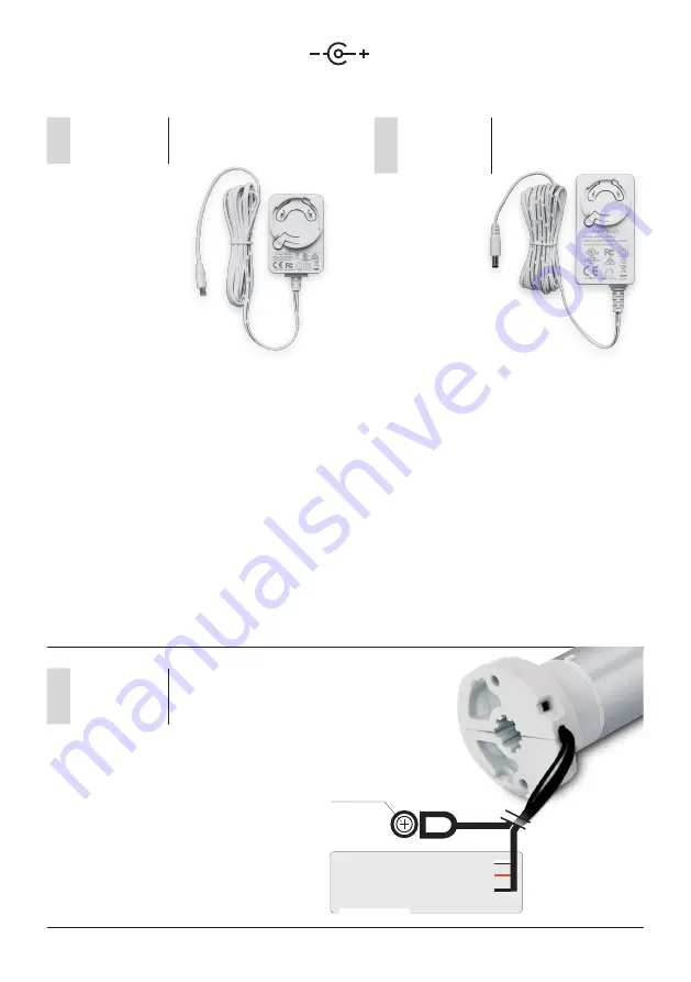
Battery charger (cod. BC12)
Input:100-240 VAC - 50/60 Hz
Output: 12 VDC 1000 mA
Plug 3.5 x 1.35
Power supply (cod. TRASDC3)
Input:100-240 VAC - 50/60 Hz
Output: 24 VDC 2.0 A
Plug 5.5 x 2.1
Check that the mains voltage available on
the system is as shown on the label.
The motor mains connection should be
executed according to the diagram on the
next page, by qualified technicians able to
operate in compliance with the rules.
White = Com
Black = Direction of rotation 2
Orange = Direction of rotation 1
DRY CONTACT
24VDC
Positive
2
XSDC3DX128
Power operated motor
XSDC3EX228
XSDC3ED228
3
XSDC3DX228
Power operated motor
XSDC3EX228
XSDC3ED228
1
XSDC3EX030B
Li-Ion integrated battery motor
XSDC3EX226B


