GarageSmart
TM
User’s Manual
17
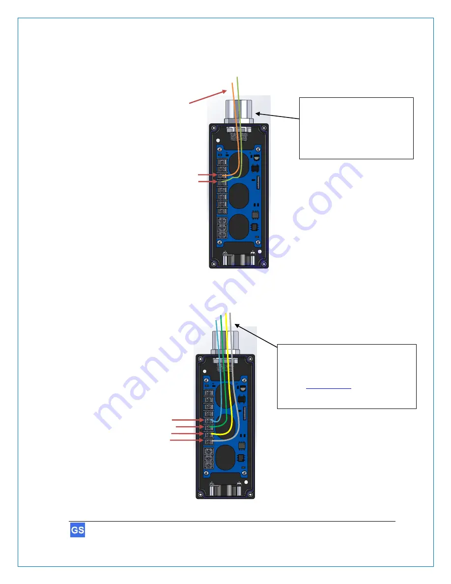
4. Feed the sensor wires through the opening of the GarageSmart
™
device and then
connect to the
and
SENSOR -
pins of the 10-Pin terminal block (polarity
doesn’t matter), using a screw driver.
5. Feed the
OPEN
,
CLOSE
,
STOP
and
COM
wires through the opening of the
GarageSmart
™
device and then connect to the 10-Pin terminal block using a screw
driver, as shown below.
Sensor Wires
Wires connect to the
OPEN
,
CLOSE
,
STOP
and
COM
terminals of the garage
door motor control board.
See the
this section for further information on how
to connect these connections.
24V +
24V –
SENSOR –
OPEN
CLOSE
STOP
COM
AUX NO
AUX COM
AUX NC
Note:
Using ¾” Conduit and a Lock Washer
(shown above) is a typical application
in securing and sealing the wires
entering the GarageSmart device.
24V +
24V –
SENSOR –
OPEN
CLOSE
STOP
COM
AUX NO
AUX COM
AUX NC


