D
RIVE
N
UT
R
EPLACEMENT PROCEDURE
G
ENESIS
2006
arts required:
•
35106 Drive Nut Assembly (1)
•
12857 Greaser (Recommended) (1)
•
35105 Brass Safety nut. (1)
rocedure:
•
Run the lift so that you have access to the drive nut. It is best to run the platform
to the bottom. The back wall must then be removed. It may be necessary to
remove the platform as well.
•
Turn off the power and lock it.
•
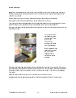
Disassemble the upper top and bottom bearings on the screw. The Drive Nut
cannot be removed without raising Lead screw up high enough to “unscrew the
Safety and Drive Nuts off the end.
•
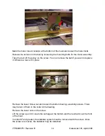
Disconnect the greaser hose to the drive nut and remove the safety switch so
that it is not damaged. CAUTION! The old greaser will continue to produce
grease. Be ready to catch the excess grease. Smear it onto the drive screw.
•
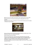
Turn the Lead screw so that it ascends above the nuts and their supporting
frames in the cross-member of the carriage.
•
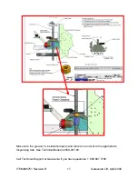
Note the distance between the Drive nut and safety nuts is around 6 to 5 mm or
one full turn of the screw. This will have to be checked once the drive nut is back
in place.
•
When replacing the Drive Nut, we always replace the Safety Nut as well due to
the inherent work involved.
•
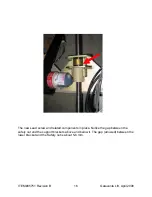
Make sure the safety switch is properly positioned so that it will activate if the
drive nut fails.
•
Turn the lead screw so that it descends down to its original position.
•
Install the new Greaser and turn it on and reset the safety switch to its original
position.
P
P
•
Put lots of grease onto the threads of the screw.
•
Re-assemble the lift and check its operation.
•
Return the lift to service.
ITEM #05751 Revision B
Garaventa Lift, April 2008
11


