background image

PP610/612 LED lighting controllers - User Manual

9

Operation

The PP610 can be set up using the push buttons and display on the front
of the unit. The setup is non-volatile, so the PP610 will resume the same
operation after a power cycle.

9.1

Startup

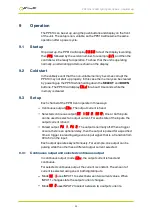
On power up, the PP610 will display

8

.

8

.

8

.

8

.

to test the display is working,

then

PP6

, followed by the version number, for example

017

, and then the

controller will be ready for operation. To show that the unit is operating
normally, an alternating pattern is shown on the display.

9.2

Cold start

In the unlikely event that the non-volatile memory becomes corrupt the
PP610 may not start up properly. In this case the memory can be cleared
by powering up the PP610 while holding down the

SELECT

and

DOWN

buttons. The PP610 will display

COLD

for about 10 seconds while the

memory is cleared.

9.3

Set up

Each channel of the PP610 can operate in three ways:

Continuous output (

CON

): The output current is fixed.

Selected continuous output (

SE 1

,

SE 2

,

SE12

): One or both inputs

can be used to select an output current. For each state of the inputs, the
output current is fixed.

Pulsed output (

PU 1

,

PU 2

): The output is normally off. When a trigger

occurs, there is an optional delay, then the output is pulsed for a specified
time. A trigger is a leading edge on an input signal; that is, a transition from
0V to 5V on the input.

Each output operates asynchronously. For example, one output can be
pulsing while the other has a different output current selected.

9.3.1

Continuous output and selected continuous output

In continuous output mode (

CON

), the output current is fixed and

continuous.

For selected continuous output, the current is constant. The amount of
current is selected using one or both digital inputs.

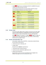
Mode

SE 1

uses INPUT1 to select between two current values. When

INPUT1 changes state the output current changes.

Mode

SE 2

uses INPUT2 to select between two output currents.

25

Summary of Contents for PP610

Page 1: ...PP610 612 LED Lighting Controllers Issue 015 User manual www gardasoft com...

Page 2: ...his equipment cannot cause any dangerous situation or significant financial loss to occur Deliberate acts of endangerment and vandalism are not covered by this document and must be considered by the i...

Page 3: ...onnections 19 8 1 PP610 serial connector 20 8 2 PP612 CCS connectors 21 8 3 Power supply 22 8 3 1 Single supply applications 22 8 3 2 Split supply applications 24 9 Operation 25 9 1 Startup 25 9 2 Col...

Page 4: ...PP610 612 LED lighting controllers User Manual 10 4 Pulsed mode output 43 11 Reference information 45 12 Timings 46 12 1 Selected continuous mode 46 12 2 Pulse mode 46 13 Error codes 47...

Page 5: ...ote that the supply voltage must be connected to three terminals When the PP610 powers up it should show two alternating lines on the display to indicate that it is operating properly Read Section 9 O...

Page 6: ...o connect the outputs correctly and protect the output wiring and load from any short circuits When switched off energy remains stored in the PP610 for about 15 seconds The PP610 does not have complet...

Page 7: ...roller must be externally fused to 4A using a slow blow fuse T4AH 50V The installer must provide a clearly marked nearby and easily accessible switch as part of the installation to allow the controlle...

Page 8: ...hentliche Ber hrung durch das Personal ausgeschlossen ist und stellen Sie sicher dass Luft frei um das Ger t zirkulieren kann 3 2 Elektrik Das PP610 erzeugt Impulse mit hoher Energie Achten Sie darauf...

Page 9: ...sofern angebracht gesch tzt sein Die Verkabelung der Stromversorgung zur Steuerung muss f r min destens 4 A bemessen sein Die Verkabelung vom Kanalausgang zur Last muss h her als der maxi male Kanala...

Page 10: ...ts beeintr chtigt werden 3 4 Installationsanleitung Haftungsausschluss Diese Informationen dienen nur zur Orientierung Installationstechniker m ssen ihre eigene spezifische Risikobewertung f r die jew...

Page 11: ...e pas de le toucher par accident et veillez ce que l air circule librement autour de l unit 4 2 lectricit Le PP610 produit des impulsions d nergie lev es Veillez bien raccorder les sorties et ce que l...

Page 12: ...tie de la cha ne la charge doit avoir une capacit sup rieure au courant de sortie maximal de la cha ne Si le contr leur est mal r gl ou en cas de panne l nergie fournie par l alimentation au contr leu...

Page 13: ...ment titre indicatif Les installateurs doivent effectuer leur propre valuation des risques pour chaque installation M me si Gardasoft Vision Ltd a pr par minutieusement ces conseils Gardasoft Vision L...

Page 14: ...large variations in light output Currents can be specified in 0 25mA steps below 1A and in 1mA steps above 1A Three modes of operation are provided separately for each channel Continuous In continuou...

Page 15: ...into the enclosure by more than 6mm The enclosure of the PP610 is used to dissipate power in the form of heat For this reason the material to which the unit is attached must be suitable preferably met...

Page 16: ...PP610 together Chose a PSU that limits its output current by design by setting the current limit on the supply if this feature exists or use fuses Remember to de rate the fuse if mounted in an enclos...

Page 17: ...L Voltage across the light LD1 and LD1 for output 1 This is usually easy to calculate as the voltage across the light is normally the voltage rating of the light as declared in its specification Alter...

Page 18: ...than 10W no heatsinking is required If the heat output is between 10W and 24W the PP610 needs to be mounted on a solid piece of metal to dissipate the heat Above 24W it is necessary to have a large h...

Page 19: ...The power connector has the following connections Screw terminal ID Function GND1 Channel 1 Power supply VS1 Power supply LD1 Load LD1 Load VS Digital power supply GND Digital power supply GND LD2 Ch...

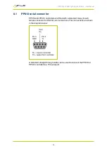
Page 20: ...tor PP610 and PP612 controllers are fitted with a standard 9 way D sub female connector for RS232 communications The connections are shown in the diagram below A standard straight through cable can be...

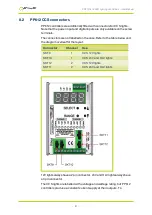
Page 21: ...not labelled on the case Refer to the table below and the diagram overleaf for the layout Connector Channel Use SKT9 1 CCS 12V lights SKT10 1 CCS 24V and HLV lights SKT12 2 CCS 12V lights SKT11 2 CCS...

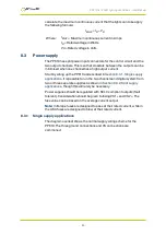
Page 22: ...Section 8 3 1 Single supply applications It is possible to run the two channels and digital system from two or three separate supplies as shown in Section 8 3 2 Split supply applications though this w...

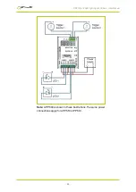
Page 23: ...PP610 612 LED lighting controllers User Manual Note A PP600 is shown in these illustrations The same power connections apply for a PP610 or PP612 23...

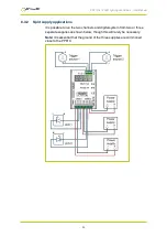
Page 24: ...supply applications It is possible to run the two channels and digital system from two or three separate supplies as shown below though this will rarely be necessary Note It is essential that the grou...

Page 25: ...l of the PP610 can operate in three ways Continuous output CON The output current is fixed Selected continuous output SE 1 SE 2 SE12 One or both inputs can be used to select an output current For each...

Page 26: ...off by default When a trigger is received on one of the digital inputs the PP610 will wait for a delay period and then pulse the output The delay period pulse width and pulse current are all configura...

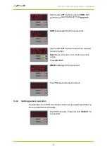
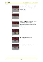
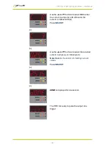
Page 27: ...ry default the maximum rating is set to 4A 9 3 5 Setting numeric values When the PP610 displays numeric values for the user to change the right hand digit flashes to indicate that the p and q buttons...

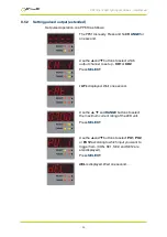
Page 28: ...and q buttons to select the required current in Amps Note Refer to Section 9 3 5 Setting numeric values Press SELECT dONE is displayed for one second The PP610 sets the output current 9 4 2 Setting p...

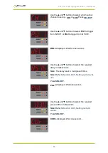
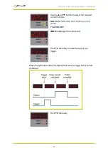
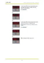
Page 29: ...T2 DEL is displayed Wait for one second Use the p and q buttons to select the required delay in milliseconds Note The delay is set in multiples of 20ms Note Refer to Section 9 3 5 Setting numeric val...

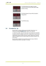
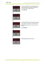
Page 30: ...he required current in Amps Note Refer to Section 9 3 5 Setting numeric values Press SELECT dONE is displayed for one second The PP610 is ready to pulse the output on a trigger When the lights are pul...

Page 31: ...o be set up It is entered by holding the RANGE button down for one second In order for the whole range of timing values to be entered it is necessary to specify whether the delay is in seconds or mill...

Page 32: ...ct which output channel to set up CH1 or CH2 Press SELECT rAT is displayed Wait one second Use the p q and RANGE buttons to select the maximum current rating of the LED unit Press SELECT Use the p and...

Page 33: ...the current in Amps a or C 3 to enter the current in milliamps b Press SELECT a b Use the p and q buttons to select the required current in Amps a or milliamps b Note Refer to Section 9 3 5 Setting n...

Page 34: ...d q buttons to select which output channel to set up CH1 or CH2 Press SELECT rAT is displayed Wait one second Use the p q and RANGE buttons to select the maximum current rating of the LED unit Press S...

Page 35: ...ct d0 to enter the delay in seconds a or d 3 to enter the delay in milliseconds b Press SELECT a b Use the p and q buttons to select the required delay in seconds a or milliseconds b Note Refer to Sec...

Page 36: ...enter the pulse width in seconds a or P 3 to enter the pulse width in milliseconds b Press SELECT a b Use the p and q buttons to select the required pulse width in seconds a or milliseconds b Note Ref...

Page 37: ...t in amps a or C 3 to enter the current in milliseconds b Press SELECT a b Use the p and q buttons to select the required current in amps a or milliamps b Note Refer to Section 9 3 5 Setting numeric v...

Page 38: ...ut channel to be specified For these the channel number either 1 or 2 immediately follows the two letter command Where more parameters are needed they consist of a single upper case letter defining th...

Page 39: ...he settings to memory AW Once the settings are saved to memory they are then retained when the unit is switched off If this is not done changes to the settings are volatile and if the unit is switched...

Page 40: ...s 1 and 2 and Output channel 2 set up to pulse a current of 5 35A for 100ms using input 1 as a trigger and a delay of 15ms with a de bounce period of 20ms The result of the ST command will be 01 M 06...

Page 41: ...us current Set the output current RCfCcVvEe Where f output channel 1 or 2 c output selection Set to 0 for non selected operation v output current in milliamps e maximum current rating of the LED This...

Page 42: ...nd must be sent for all output selections specified by the mode command If a single input is selected two current settings are needed for selections 0 and 1 If both inputs are selected four current se...

Page 43: ...and will not allow a delay to be set which is less than the minimum for the current setting When changing current and delay values it may be necessary to use the RT command to set the delay to a highe...

Page 44: ...ting of the LED This is optional if not required omit Ee from the command In the following example output channel 1 is set to pulse a current of 5 35A for 9ms triggered by input 1 with a delay of 8ms...

Page 45: ...ble level IPH Input disable level IPL 24 IPH 4 5V IPL 1V This is the voltage applied between the anode and cathode of each optically isolated input Output current per channel 4A continuous or10A pulse...

Page 46: ...ven for channel 1 and assume a trigger input signal of 5V The delays are approximately 8 s shorter for a 24V trigger input The delays for channel 2 are greater All timings are given in microseconds Pr...

Page 47: ...E16 When the unit has powered up the non volatile memory was corrupt and has been cleared Set up the unit again E25 E26 The PP610 is calibrated during manufacture This stored calibration has become i...

Page 48: ...PP610 612 LED lighting controllers User Manual Code Meaning E17 E40 E41 E64 E65 E67 E74 An internal software error has occurred Make a note of the number and contact your distributor 48...

Page 49: ...PP610 612 LED lighting controllers User Manual This page is left blank for your notes 49...

Page 50: ...ay 2017 Copyright 2017 Gardasoft Vision Ltd Gardasoft Vision Ltd Trinity Court Buckingway Business Park Cambridge CB24 4UQ UK tel 44 1954 234970 fax 44 1954 231567 Gardasoft LLC Oak Ridge Road Weare N...

Reviews: