TR-RT LED lighting controllers - User Manual
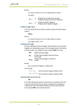
Where:
c
= output channel (1 to 2 or 4, depending on model)
m
= flags:
bit 1 =
0
1
E flag set (error detection enabled)
E flag cleared (error detection disabled)
bit 2 =
0
1
P flag set (positive triggers)
P flag cleared (negative triggers)
Set the Trigger Input
This command sets which input is used for pulse and switch output
modes.
RPc,p
Where:
c
= output channel (1 to 2 or 4, depending on model)
p
= trigger input (1 or 2)
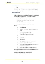
Set Internal Trigger
Enable or disable the internal trigger. When enabled, all outputs are
triggered simultaneously using an internal trigger signal. This setting
can be saved to non-volatile memory using the
AW
command.
TT0
Disable internal trigger
TT1
Enable internal trigger (uses previously
set period)
TT1,p
Enable internal trigger and set the
period
Where:
P
= period of the triggers in milliseconds
For example:
TT1,200
Set the internal trigger to 200ms (5Hz)
TT1,500US
Set the internal trigger to 500μs (2KHz)
Save the settings to memory
AW
Once the settings are saved to memory they are retained when the
unit is switched off. If this is not done, changes to the settings are
volatile, and if the unit is switched off they revert to those in force
when the last
AW
command was issued.
—
33
—

