background image

 10

2.7 Drop Application with external tubing  

The manual dispenser supplied with your instrument is designed for water and other liquids of 
similar viscosity. Test liquids of high viscosity (e.g. glycerine, floor varnish) can not be 
applied with the manual dispenser. To apply liquids of high viscosity the procedure below can 
be used. This procedure can also be used for temporary testing with “unusual” liquids, as it 
will not require cleaning of the dispenser.  

The procedure below uses an optional syringe with tip (PN # 860 321). The same procedure 
can also be used with the manual dispenser delivered with the instrument. 
 
PLEASE NOTE! To avoid contamination it is recommended to use separate tubing for each 
test liquid. 


a)  Hold the top section of the tubing dispenser and turn the lower 

part a few turns to open the chuck inside.  
 

b)  Insert the applicator tubing into the dispenser without touching 

the free end. Leave approx. 25 mm of the tubing outside the 
dispensing tip.   


c)  Fit the other end of the tubing onto the RED syringe tip and 

push the tip onto the syringe. 
 

d)  Push the plunger inside the syringe to its forward position. 
 
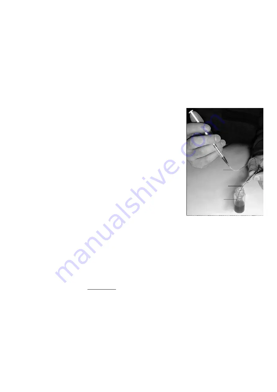
e)  Insert the free end of the applicator tubing into the test liquid. 

DO NOT dip the dispensing tip into the liquid!


f)  Pull the plunger gently backwards to fill the tubing.  

DO NOT let the liquid enter the syringe tip! 


g)  Remove tubing end from the liquid container and pull the 

plunger slightly backward to suck some air into the tubing end. 
 

h)  Wipe the outside of the tubing end clean.  
 
i) 

Pull the tubing into the dispenser until only a short end (approx. one mm)  

extends outside the tip of the dispenser. Tighten the chuck gently to lock the tubing.  
 

j)   Install the dispenser in the instrument. 


k)  Load a specimen as described in Section 2.2. 
 
l)   Push the plunger very carefully forward until a droplet appears at the dispensing tip.  

Press on top of the dispenser to apply the droplet on the specimen. 


m)


Advance the specimen to a new test position. Pump out a new droplet as described in (l)  
above and apply it on the surface for the first test droplet.

Fig. 2.19 Fill the tubing 

(f

(b

(e

Summary of Contents for PG-1

Page 1: ...P A U L NG A R D N E RC O MP A N Y 9 1 0 4G U I L F O R DR O A D S U I T E H E MA I L G A R D C O A L T A N A C O M C O L U MB I A MD2 1 0 4 6U S A P H O N E 1 9 5 4 9 4 6 9 4 5 4...

Page 2: ...The PocketGoniometer Model PG 1 User s Manual...

Page 3: ...0 degrees 2 6 3 Contact Angles above 90 degrees 2 6 4 A Perfect Sphere 2 7 Drop Application with external tubing 3 Static and Dynamic Contact Angles 3 1 Static Contact Angle 3 2 Dynamic Contact Angle...

Page 4: ...on a specimen surface a contact angle is formed at the contact area By definition a droplet which beads up is non wetting and a contact angle higher than 90 degrees is displayed When the droplet wets...

Page 5: ...ecimen strips of up to 2 5 mm thickness Thicker specimens up to 12 mm can be tested if the specimen stage is removed in the following way a Remove the two screws accessible through the holes at the bo...

Page 6: ...spensing unit with the tip pointing upwards and tap gently on the dispenser to bring air bubbles inside the liquid to the top Push the plunger slightly forward to remove the air at the tip Rotate the...

Page 7: ...act two different situations may occur which can be described as a released droplet Figure 2 5 which is immediately transferred to the specimen upon contact with the surface a trapped droplet Figure 2...

Page 8: ...age sideways or simply reduce the droplet size when this can be done 2 6 Taking a reading First of all the protractor disk must be rotated into the correct position In general the objective is to matc...

Page 9: ...ay to measure the contact angle on a droplet shape like this is to a Rotate the protractor until centre line is at 90 degrees b Locate the point of reflection on the droplet at the edge of the contour...

Page 10: ...of reflection is aligned with the centre line PLEASE NOTE It is important the point of reflection to be positioned exactly at the centre line d Locate the top of the droplet and rotate the protractor...

Page 11: ...the dispensing tip c Fit the other end of the tubing onto the RED syringe tip and push the tip onto the syringe d Push the plunger inside the syringe to its forward position e Insert the free end of...

Page 12: ...PocketGoniometer model PG 1 3 3 The Dynamic Contact Angle function of time When the liquid spreads across or penetrates into the substrate the contact angle will change continuously This dynamic cont...

Page 13: ...re Reverse flow a Cut a specimen Section 5 and install it on the specimen stage Section 2 2 The specimen surface should be viewed slightly from above b Fill the manual dispenser with the preferred tes...

Page 14: ...of the specimen e g MD CD and 45 Specimens up to 12 mm thickness can be tested if the specimen stage is removed as described in Section 2 1 2 d Soft materials films or warping materials should be moun...

Page 15: ...your supplier for adjustment or repair of the lens No droplet or droplets of varying size appear at the dispensing tip Check for air bubbles inside the Manual Dispenser 8 Technical Specifications Spe...

Page 16: ...s of the carrier strip c Remove the release paper on top of the adhesive strip The top side is now the soft adhesive which can be used for multiple specimen strips d Cut a 14 15 mm wide specimen strip...

Page 17: ...16 PG 1 User s Manual 1 2a ENG Copyright 2003 FIBRO System AB Sweden...

Reviews: