background image

English - 25

3. INSTALLATION

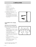
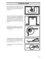
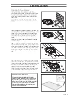
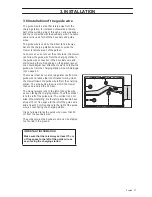
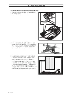
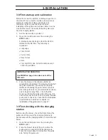
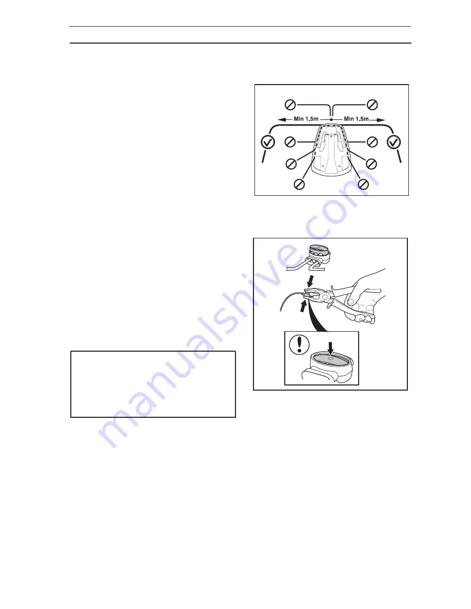
Laying the boundary wire in towards the charging 
station 

The boundary wire must be laid in line with the rear 
end of the charging station. If the boundary wire is 
laid in any other way, R40Li may find it hard to enter 
the charging station.

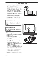
In many cases, the straight wire section to the left of 
the charging station can be reduced to 1 metre. 

Depending on how the boundary wire is laid in the 
rest of the installation, the straight wire section to the 
right of the charging station may need to be extended 
in certain cases. 

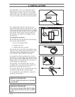
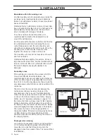
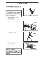
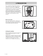
Joining the boundary wire

Use an original coupler if the boundary wire is not 
long enough and needs to be spliced.It is waterproof 
and gives a reliable electrical connection. 

Insert both wire ends in the coupler. Make sure the 
wires are fully inserted in the coupler by checking 
that the wire ends are visible through the transparent 
area on the other side of the coupler. Now press 
down the button on top of the coupler fully. Use a pair 
of pliers if the button on the coupler is difficult to 
press down by hand.

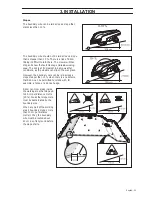
IMPORTANT INFORMATION

Twinned cables, or a screw terminal block 
that is insulated with insulation tape are not 
satisfactory splices. Soil moisture will cause 
the conductors to oxidise and after a while 
result in a broken circuit.

Summary of Contents for R40Li

Page 1: ...Operator s Manual GARDENA Robotic Lawn Mower R40Li...

Page 2: ......

Page 3: ...ery 33 4 2 Using the timer 34 4 3 Starting 35 4 4 Stopping 35 4 5 Switching off 35 4 6 Adjusting the cutting height 35 5 Control panel 36 5 1 Operation selection 37 5 2 Multi choice buttons 38 5 3 Num...

Page 4: ...GARDENA Central Service and provide the mower s serial number and product registration key so that it can be registered as stolen in an international database This is an important step in the mower s...

Page 5: ...stem is used in the Operator s Manual to make this easier Text written in italics is a text that is shown on the mower s display or is a reference to another section of the Operator s Manual Words wri...

Page 6: ...PIN code has been entered Inspection and or maintenance must be carried out with the main switch set to 0 Remain at a safe distance from the R40Li when it is running Keep your hands and feet away fro...

Page 7: ...he mower s underframe Never use a high pressure washer or even running water to clean R40Li A warning box indicates a risk of personal injury exist especially when the stated instructions are not foll...

Page 8: ...position make sure to keep your hands and feet away from the rotating blades Never put your hands and feet under the mower Never lift up R40Li or carry it around when the main switch is in the 1 posi...

Page 9: ...lade disc away from the body Maintenance Inspect R40Li each week and replace any damaged or worn parts Check especially that the blades and blade disc are not damaged Replace all blades and screws at...

Page 10: ...Sending control signals in the guide wire so that R40Lican find the charging station To charge R40Li battery Transformer which is connected between the charging station and a 230V wall socket The tran...

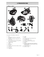
Page 11: ...Chassis box with electronics battery and motors 11 Main switch 12 Rear wheel 13 Charging strip 14 Keypad 15 Display 16 Loop wire for boundary wire and guide wire 17 Low voltage cable 18 Connector for...

Page 12: ...technique The mowing system used by R40Li is based on an effective and energy efficient principle Unlike normal robotic lawn mowers R40Li cuts the grass instead of striking it off We recommend you al...

Page 13: ...ly selected direction within the 90 to 270 exit sector To ensure an even cut even in inaccessible parts of the garden the lawn mower can follow the guide wire out from the charging station to where th...

Page 14: ...on page 42 for more information on theft protection Movement pattern The mower s movement pattern is irregular and is determined by R40Li itself A movement pattern is never repeated This mowing syste...

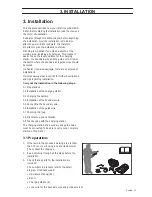
Page 15: ...urther descriptions and tips regarding installation Carry out the installation in the following steps 3 1 Preparations 3 2 Installation of the charging station 3 3 Charging the battery 3 4 Installatio...

Page 16: ...lowing aspects into consideration when identifying the best location for the charging station Allow for 3 metres of free space in front of the charging station It must be possible to lay at least 1 5...

Page 17: ...traight out from the rear end of the charging station Any other locations can mean that the lawn mower enters the charging station sideways and will have difficulty docking Do not put the charging sta...

Page 18: ...ction from direct sunlight If the transformer is connected to an electrical socket outdoors this must be approved for outdoor use The low voltage cable to the transformer is 10 meters long and may not...

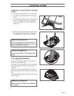
Page 19: ...ng the battery As soon as the charging station is connected it is possible to charge the mower The mower can be charged as soon as the charging station is connected Set the main switch to the 1 positi...

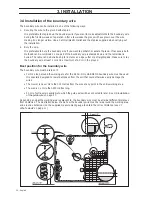
Page 20: ...or a straight spade Make sure to lay the boundary wire at least 1 cm and a maximum of 20 cm in the ground Best position for the boundary wire The boundary wire must be laid so it Forms a loop around...

Page 21: ...or the like that lies level with the lawn it is possible to allow R40Li to run a little over the path The boundary wire should then be laid 5 cm from the edge of the path All the grass along the side...

Page 22: ...ged Secondary areas If the working area consists of two areas which the mower has difficulty travelling between it is recommended to set up a secondary area Instances of this are 25 slopes or a passag...

Page 23: ...conditions as the wheels can slip on the wet grass However the boundary wire can be laid across a slope steeper than 10 when there is an obstacle that R40Li can be permitted to collide with for exampl...

Page 24: ...e wire in sharp bends If the boundary wire is to be buried Make sure to place the boundary wire at least 1 cm and a maximum of 20 cm into the ground The wire can be buried for instance using an edge c...

Page 25: ...ses Joining the boundary wire Use an original coupler if the boundary wire is not long enough and needs to be spliced It is waterproof and gives a reliable electrical connection Insert both wire ends...

Page 26: ...ective connectors 4 Press the connector onto the contact pin marked A on the charging station Carefully check that the connector is properly fitted IMPORTANT INFORMATION The boundary wire must not be...

Page 27: ...station See 6 5 Settings 3 on page 43 The mower must be run at varying distances from the guide wire to reduce the risk of tracks forming when the mower follows the guide wire to from the charging st...

Page 28: ...t pin on the charging station that is labelled guide 3 Route the guide wire at least 2 metres straight out from the front edge of the charging plate If the guide wire must be laid in a passage the R40...

Page 29: ...ge to lay the wire at an angle to the slope This makes it easier for the mower to follow the guide wire on the slope Avoid laying the wire at sharp angles This can make it difficult for the mower to f...

Page 30: ...gnal Flashing yellow light interruption in the guide wire no guide signal Flashing red light interruption in the charging station s antenna plate no remote signal available Contact GARDENA Central Ser...

Page 31: ...display The mower will now start the guide calibration by leaving the charging station and following the guide wire to the point where the guide wire is connected to the boundary wire to begin mowing...

Page 32: ...mpt If the mover is unable to dock on the first attempt it will automatically try again The installation is not approved if the mower needs two or more attempts to dock with the charging station In th...

Page 33: ...witch to the 1 position 2 Place R40Li in the charging station Open the cover and slide the mower in as far as possible to ensure proper contact between the mower and the charging station 3 The display...

Page 34: ...ower begins cutting the lawn at 07 00 The mower is parked in the charging station from 22 00 and rests until it starts cutting again at 07 00 Example 2 Work hour 1 06 00 16 00 Work hour 2 20 00 23 00...

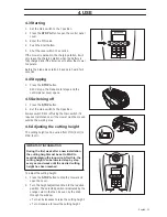
Page 35: ...he main switch if it requires maintenance or if the mower must be moved outside the working area 4 6 Adjusting the cutting height The cutting height can be varied from MIN 2 cm to MAX 5 cm To adjust t...

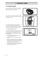
Page 36: ...nt time Date shows the current day The number of operating hours indicates the number of hours since the day of manufacture that R40Li has been in operation The time that R40Li has spent mowing or loo...

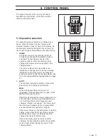
Page 37: ...ollow the guide wire and dock with the charging station See 3 9 Test docking with the charging station on page 31 2 AUTO The standard automatic operation mode where R40Li mows and charges automaticall...

Page 38: ...helps you to scroll the menu 5 3 Numbers The number keys are used for instance to enter the PIN code or time settings The number keys can also be used to enter a number series for shortcuts to the va...

Page 39: ...selection button pressed in for 2 seconds to go directly back to the main menu Number series A number series can be used as a shortcut to a certain function The first number in the series refers to t...

Page 40: ...ttings Work hour 1 Work hour 2 Work days Security Change PIN code Security level New loop signal Language Time Date Backlight Low Medium High Set date Date format Set time Time format Reset timer Cali...

Page 41: ...s for operating period 1 Enter each required time in hours and minutes and press OK to confirm the entered time Work hours 2 1 2 to set start and stop times for operating period 2 Enter each required...

Page 42: ...orrect PIN code is not entered after a designated time period Time lock This function entails that R40Li cannot be started after 30 days without first entering the correct PIN code When the 30 days ha...

Page 43: ...milar signal Park the mower in the charging station Select New loop signal in the menu and press OK 6 5 Settings 3 The following operating settings are available via this selection in the main menu Ti...

Page 44: ...r Press OK to exit Language 3 2 Set language with this function To select language Place the cursor at Language and press OK Place the cursor at the required language and press OK Backlight 3 3 To ind...

Page 45: ...int How often it must follow the guide wire from the charging station is selected as a proportion of the total number of times it leaves the charging station At all other times the mower leaves the ch...

Page 46: ...h the boundary wire The test has failed if the mower cannot follow the guide wire all the way to the connection point with the boundary wire It is likely that the installation has not been carried out...

Page 47: ...ens with installation and setting proposals There are also animated garden examples on www gardena com int For more detailed information about the various settings see chapter 6 Menu functions IMPORTA...

Page 48: ...setting Place the charging station in the lower part of the working area Lay the guide wire at an angle over the steep slope Area Timer Proportion Remarks 200 m2 L shaped garden with charging station...

Page 49: ...rical working area with a narrow passage and a number of islands 07 00 17 00 Monday Tuesday Wednesday Friday Rarely factory setting The guide wire must be placed along the narrow passage to ensure the...

Page 50: ...easily The edges of the blades should not be damaged The product life of the blades varies immensely and depends for instance on Operating time and size of the working area Type of grass Type of soil...

Page 51: ...son Store the mower upright in a dry area free from frost preferably in the mower s original packaging Charging station Store the charging station and transformer indoors The boundary wire can be left...

Page 52: ...e may impede the blade disc Even a slight braking effect leads to a higher consumption of energy and longer mowing times and at the worst will prevent the mower from being able to mow a large lawn Cha...

Page 53: ...blades on R40Li which are screwed into the blade disc All three blades and screws must be replaced at the same time to obtain a balanced mowing system Use GARDENA approved blades only To replace the...

Page 54: ...tion 3 Turn the mower upside down Place the mower on a soft and clean surface to avoid scratching the body and the display cover 4 Clean around the battery cover 5 Unscrew the four screws to the batte...

Page 55: ...heck the blade disc and remove the grass or other object The blade disc lies in a pool of water Move the mower and if possible prevent the collection of water in the working area No loop signal The tr...

Page 56: ...ment steel or buried cables close by Try moving the boundary wire The mower finds it hard to distinguish the signal from an R40Li installation close by Park A in the charging station and generate a ne...

Page 57: ...de a number of charging attempts Place R40Li in the charging station and check that the charging strips and contact strips make good contact An object is obstructing R40Li Remove the object Stuck in c...

Page 58: ...breaks in the loop wire on page 61 Yellow flashing light The guide wire is not connected to the charging station Check that the guide wire connector is properly connected to the charging station See 3...

Page 59: ...rging station is on a slope Place the charging station on a surface that is entirely level See 3 2 Installation of the charging station on page 16 Uneven mowing results R40Li works too few hours per d...

Page 60: ...mower is searching for the charging station The mower mows for shorter periods than usual between charges Grass or other foreign object blocks the blade disc Remove and clean the blade disc See 8 3 Cl...

Page 61: ...has been reached A defective splicing of the loop cable can also lead to disruptions first several weeks after the splice was formed A faulty splice can for example be the result of the original coupl...

Page 62: ...e break is somewhere on the boundary wire between A1 and the point where the guide wire is connected to the boundary wire thick black line in the illustration b Put A1 and Guide back in their original...

Page 63: ...here at the centre of the installation If the indicator lamp is green or flashing yellow then the break is somewhere in the wire between the disconnected end to the point where the new wire is connect...

Page 64: ...a solid green light b If the indicator lamp flashed yellow in test 3b above a similar test is carried out but with the new loop wire connected to A1 instead 5 When the break is found the damaged sect...

Page 65: ...46 cm Height 26 cm Weight 8 kg Electrical system Battery Specialised Lithium Ion battery 18 V 1 6 Ah Transformer 230 VAC 21 6 VDC Mean energy consumption at maximum use 7 kWh month with a working are...

Page 66: ...not a GARDENA original battery Damage to the loop wire The knives are seen as disposable and are not covered by the guarantee If an error occurs with your GARDENA R40Li please contact GARDENA Central...

Page 67: ...text on the rating plate with subsequent serial number complies with the requirements of the COUNCIL S DIRECTIVE Directive relating to machinery 2006 42 EC Directive relating to electromagnetic compa...

Page 68: ......

Page 69: ......
Page 70: ...We reserve the right to make changes without prior notice Copyright 2012 GARDENA Manufacturing GmbH All rights reserved 115 42 61 26...

Reviews: