background image

Summary of Contents for Electra-Saver EAU P Series

Page 1: ...603 13 10 603 1st Edition Originally Published As 13 9 616 3rd Edition ELECTRA SA VERB STATIONARY SCREW COMPRESSOR MODELS EAU P 200 HP EA U Q 250 HP EAU_R 300 HP SERIAL NUMBER u A GARDNER DENVER COOP...

Page 2: ...LECTRA SAVEW EB ET ELECTRA SCREW SE ST PACKAGES Anyproduct which haS inthe Compan s judgment been subject to negtigencq accident improper atoragq or improper installation or application Any product wh...

Page 3: ...tice could result in injuty to or death of personnel A WARN NG Failure toob5eme a WARNING notice could result in damage to equipment ACAUTION CAUTION notices set forth general reminders of good safety...

Page 4: ...ystem Check 5 7 COMPRESSOR OVERHAUL Refer to Manual 13 9 625 Constant Speed Control System With Low Demand Mode 4 8 Constant Speed Opeation 4 9 Control Check Valve Flow 4 9 Control Compre or Capacity...

Page 5: ...ssure Differential 5 8 Oil Filter Compressor 5 4 Oil Filter Indicator 4 5 OIL FILTER SEPARATOR OIL COOLER LUBRICATION SECTION5 5 1 Oil FIOW Diagram Remote Overhead Mounted Oil Cooler 5 2 Oil Inlet Pre...

Page 6: ...ischarge Air 4 5 Thermal Control Thermostatic Mixing Valve 5 4 Thermostatic Mixing Valve Thermal Control 5 4 Three Way Valve 4 9 Time Delay Switch Low Oil Pressure 4 4 Turn Valve 1 1 4 5 Turn Valve Ac...

Page 7: ...educed and pressure in creases Oil is injected into the cylinder to remove the heat of compression and seal internal clearances Volume DISCHARGE PORT K m NJ l c reduction and pressure increase continu...

Page 8: ...13 10 603 Section 1 Page 2...

Page 9: ...ICALLY NEVER BYPASS SAFETY DEVICES A DANGER KEEP FINGERS AND CLOTHING AWAY FROM REVOLVING FAN DRIVE COUPLING ETC DO NOT USE THE AIR DISCHARGED FROM THIS UNIT FOR BREATHING NOT SUITABLE FOR HUMAN CONSU...

Page 10: ...ooler Discharge In Size Unit Module Same Room 200 HP 8 000 23 000 31 000 250 HP 9 900 24 000 33 900 300 HP 11 900 24 000 35 900 J 80 F Inlet Air FIGURE 2 2 MINIMUM AIR FLOW FOR COMPRESSION AND COOLING...

Page 11: ...be used in the pipe run A dimensional sketch of the proposed piping system showing location of the compressor unit oil cooler and pipe and fittings of 3 through 6 above All remote piping should be of...

Page 12: ...t air temperature or cooling water temperature Air Cooled Machines When an aftercooler is furnished on an air cooied machine the aftercooier is instaiied on the oil cooier module between the fan and t...

Page 13: ...ized for operation in these low temperatures Shutters are not a factory option 3 4 8 FT PLYWOOD FENCE N51 ELEVATION VIEW Coolers should be located as close to unit as ossible Long lines to and from th...

Page 14: ...ceiver must be located be tween the two units A DANGER DO NOT USE THE AIR DISCHARGED FROM THIS UNIT FOR BREA THING IT IS NOT SUITABLE FOR HUMAN CONSUMPTION WATER PIPING Water Cooled Heat Exchanger Mod...

Page 15: ...and add grease with a hand operated grease gun Leave the relief plug temporarily off Reconnect the unit and run for about 20 minutes to expeli the excess The water control valve MUST be used to maint...

Page 16: ...properly wired See Section 4 Controls and instru ments for general wiring diagrams and Section 2 for installation instructions Rotation Check the motor rotation by momentarily 7 8 9 starting the moto...

Page 17: ...d cooler air and oil filters the control system specified an open drip proof motor and a dust resistant control enclosure instrument panel all mounted on a steel base The compressor is isolated in an...

Page 18: ...position will blow the reservoir down when the compressor unloads When switch is turned to OFF unit will retain pressure in reservoir when unloaded WARNING The low demand mode switch CANNOT be used w...

Page 19: ...ON This a sstable switch MUST NOT be set higher than 225 F DO NOT CONTINUE TO RESET THE CIRCUIT IF THE SAME MALFUNCTION OCCURS WITHIN A SHORT PERIOD OF TIME FIND AND CORRECT THE TROUBLE BEFORE RESUMIN...

Page 20: ...h Constant Speed with Low Demand Mode Switch shuts down from low oil pressure pressing the ON button will restart the unit Since the Automatic Startflmed Stop control is an automatic starting type a r...

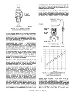
Page 21: ...type check vaive in the final discharge manifoid prevents backflow of air from the shop air line when the unit stops unioads or is shut down COMPRESSOR CAPACiTY CONTROL The capacity of the compressor...

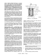
Page 22: ...sure is below set point spring pressure returns or holds valve in position to allow oil to flow to the turn valve actuator which rotates turn valve to maximum compressor capacity When discharge pressu...

Page 23: ...gure 1 4 is the same type that is used on the turn valve actuator control valve The pilot admits air to the inlet valve piston when a discharge manifold pressure equal to the pilot low setting is reac...

Page 24: ...he lower differential adjusting screw on the low demand mode pressure switch near the desired pressure Full receiver pressure minus the differential is the compressor load point The differential range...

Page 25: ...facturer s instruction manual for complete details AUXILIARY AIR RECEIVER An auxiliary air receiver with adequate volume must be used with both control systems to prevent rapid cycling of the unit Occ...

Page 26: ...FIGURE 11 4 SCHEMATIC LOW STARTING TORQUE OUTLINE CONTROL The reservoir RESERVOIR PRESSURE SWITCH pressure switch will prevent motor damage if an attempt to start motor is made before the reservoir is...

Page 27: ...A 13 10 603 Section 4 Page 11 m CD m co I W In...

Page 28: ...iii I L L _ 2 13 10 603 Section 4 Page...

Page 29: ...ill Ill Ill 111P Ill Ill d J l T O i F r Ill I T T T T r T T 13 10 603 Section 4 Page 13...

Page 30: ...UfJT r I I I u I14 I L __ i 2 7 13 10 603 Section 4 Page 14...

Page 31: ...1 u L____ 4 _ __ _J I I I 13 10 603 Section 4 Page 15...

Page 32: ...rol panel to the remote mounted starter control circuit is rated 600 volts Remote mounted magnetic compressor starter control circuits are to be connected for TWO 2 WIRE Control The remote compressor...

Page 33: ...ter with its disconnecting means When the aftercooler is sized for more than one compressor see instructions for aftercooler starter coil on the special wiring diagram or sketch THE FOLLOWING COMPONEN...

Page 34: ...I NEMA 4 I 91B3 1 1 2 91 B24 1 1 2 t Valves have manual override O L M W V S are also shown on Wiring Diagrams for Water Cooled Aftercoolers when used and are to be sized for the aftercooler if used O...

Page 35: ...starter manufacturers control hand booh digest catalog etc If the typical wiring diagram shows two or more contacts paralleling the start push button then these Aux contacts are required If the typica...

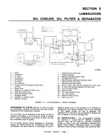
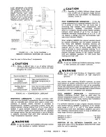
Page 36: ...MS COMPRESSOR OIL SYSTEM Figures 1 5 and 2 5 COOIS the compressor lubricates moving parts and seals internal clearances in the compression chamber The oil suction line is connected at the bottom of th...

Page 37: ...Oil Temperature Range Gardner Denver Year round operation at GD800 discharge temperatures to Lubricating Coolant 200 F Gardner Denver Over four 4 hours sustain GD8000 ed discharge temperature Lubricat...

Page 38: ...operating conditions and quality of oil Good practice is to change oil often enough that the drained oil is relatively clean Under good operating conditions Gardner Denver GD800 may be used up to 200...

Page 39: ...RESSOR OIL COOLER RADIATOR TYPE MODULE The air cooled oil cooler module is remote mounted The oil cooler requires pipe and electrical connection to the main compressor unit Connecting piping and wirin...

Page 40: ...r more of these conditions exists may result in increased maintenance and operation expense reduced equipment life and emergency shutdown It is strongly recommended that a reputable local water treatm...

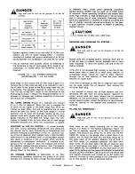
Page 41: ...reservoir consists of two re newable cartridge type separator elements and provides the final removal of oil from the air stream Oil from inside the separator elements is returned through tubing to th...

Page 42: ...h the unit on full load at rated service pressure See Compressor Oil Separator above AUTOMATIC BLOWDOWN VALVE Figure 1 5 13 10 603 A pilot actuated valve receives an air signal from a solenoid operate...

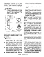
Page 43: ...l Water Cooled Heat Exchanger The oil temperature differential depends on the inlet water temperature and the water flow rate permitted by the water flow control valve setting The oil inlet temperatur...

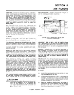
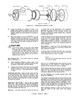
Page 44: ...e element with stream of water 40 PSI maximum opposite to normal air flow until rinse water is clear DRY ELEMENT THOROUGHLY BEFORE USING DO NOT USE LIGHT BULBS FOR DRYING Warm air 1 60 F or less must...

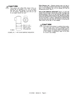
Page 45: ...s follows Dust Cup Filter Element and Filter Life Dust Cup Plan daily intervals for removal of dust CUP to inspect filter for dirt accumulation until experience determines the proper intervals This ma...

Page 46: ...FILTER SERVICE INDICATOR Figure 1 4 and 3 6 signals time to change or service the air filter The flag in the window gradually rises as the filter element loads with dirt When the pressure drop across...

Page 47: ...OWARD OUTSIDE DIAMETER OF COUPLING 3 Working through coverplate opening center coupling over gap between shafts maintaining gap as shown in Figure 1 7 between the ends of the jaws on one cou pling bod...

Page 48: ...25 Hours Operation 1 Check for dirt accumulation on oil cooler and after cooler core faces and the fan and fan motor If clean ing is required clean the exterior fin surfaces of the cores by blowing co...

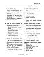
Page 49: ...lty low oil pressure shutdown switch Time delay on timing relay for low oil pressure shut down set too short a time MAXIMUM DELAY SETTING IS 15 SECONDS Timing relay setting screw not engaged a Faulty...

Page 50: ...ER COOPER INDUSTRIES INDUSTRIAL MACHINERY DIVISION 1800 GARDNER EXPRESSWAY QUINCY ILLINOIS 62305 4024 217 222 5400 Specifications subject to change without notice Sales and Service Offices in all prin...

Reviews: