


Description
The Eegor™ Bending Table is designed to provide
mounting for an Eegor™ Hydraulic Bender. The table
positions the bender off the floor for easy, precise
bending and operator comfort. Hydraulic rotation of
the table top allows the user to accurately check
bending, and to obtain precise bends with the least
amount of effort.
Bender Mounting
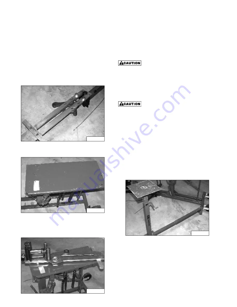
1. Turn the Eegor™ bottom load arm / cylinder assembly
upside down, as shown in Fig. 1. Remove the four (4)
flat head cap screws, freeing the two (2) rest pads and
stabilizer bar from the load arm.
2. Position table top in horizontal position as shown in
Fig. 2.
3. Line up the two (2) pads and stabilizer bar, removed in
Step 1, on the table top over the four (4) mounting
holes as shown in Fig. 3. Position the load arm
cylinder assembly on the two (2) pads and stabilizer
bar on the table top with the cylinder positioned as
shown in Fig. 3. Line up the four (4) tapped holes in the
load arm with the four (4) mounting holes in the table
top. Fasten the load arm to the table top with the four (4)
1
⁄
2
- 13 UNC x 1
3
⁄
4
long hex head cap screws supplied
with the table. Insert the cap screws through the bottom
of the table top plate through the pads and into the
tapped holes of the load arm. (Torque the cap screws to
50 ft. lbs.)
Properly support the overhanging
cylinder until the load arm / cylinder
assembly is secured to the table top.
4. The bottom load arm / cylinder assembly is now
securely mounted on the table top. Consult the
Eegor™ Hydraulic Bender instruction sheet for
complete bender set up and operating instructions.
Always provide proper support for
bender components and conduit during
set up and removal operations.
Improper support could result in a
serious injury.
Side Support Stand
The side support stand is provided to aid in the set up
and removal of the larger sizes of conduit. The stand is
attached to the bender table at a single pivot point to
provide maximum required stability while maintaining a
flexible stand position.
The correct assembly of the side support stand is shown
in Fig. 4. To attach the stand to the table, insert the pin
shown in Fig. 4 into the tube provided on the table base.
To adjust the height of the stand, loosen the L-screw
shown in Fig. 4. Move the top to the desired height and
retighten the L-screw to a firm hand tightness.
Before Bending
After the bending shoe (any size), top compression roller
assembly, top load arm, and bending shoe pivot pin
L-Screw
Figure 1
Figure 2
Figure 3
Figure 4


