5
If all cable diameters within the bundle are the same, select your
grip from Table 3.
If individual cable diameter is not known, or the cables within the
bundle are of different diameter, use Table 4.
WARNING
1. Inspect rope for damage prior to use. Do not use a damaged
rope. Using a damaged rope can result in a pull failure and
damage to the cables.
2. Inspect the pulling grip for damage prior to use. Do not use a
damaged pulling grip. Using a damage pulling grip can result
in a pull failure and damage to the cables.
FAILURE TO OBSERVE THESE WARNINGS COULD RESULT
IN SEVERE INJURY OR DEATH
9.1 PULLING UPWARD
1. Position the machine near the conduit box, leaving enough
room to unfold and properly adjust the boom structure.
2. Lock the brakes on the casters.
3. Close the Hydraulic Pump valve by turning clockwise.
Do not
over-torque.
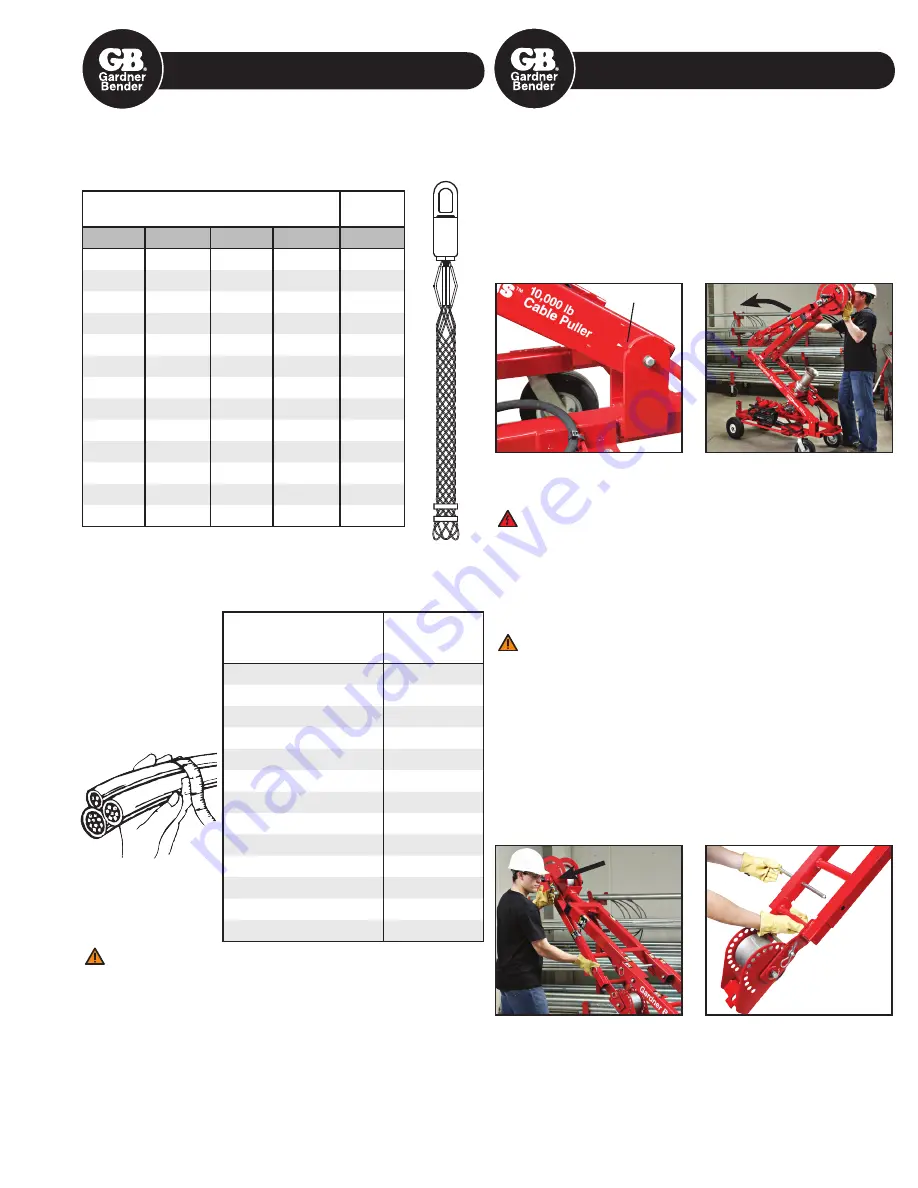
4. Release the pump handle lock and pump the Main Boom up
to a 30 degree angle. The Main Boom pivot bracket is marked
for 30 degrees. (See Picture 1)
5. Remove Boom-A Lock Pin and temporarily store in Pin Clips.
DANGER:
Check for overhead wires prior to unfolding the
boom structure.
FAILURE TO OBSERVE THESE DANGERS WILL RESULT IN
SEVERE INJURY OR DEATH
6. With one hand on the Steering Handle and one hand on
Boom-B, lift and rotate Boom-A and Boom-B together until it
stops inline with the Main Boom. (See Picture 2)
WARNING:
If you do not place your hands as instructed, then
you may crush your hand or fingers. If you do not observe the
machine warning labels, you may crush your hand or fingers.
FAILURE TO OBSERVE THESE WARNINGS COULD
RESULT IN SEVERE INJURY OR DEATH
7.
Re-insert Boom-A Lock Pin and retaining clip.
!! This is extremely important !!
8. While holding on to Boom-B securely, release the Boom-B
Lock Pin. Adjust angle of Boom-B and re-engage the
Boom-B Lock Pin to secure it.
Confirm the pin is fully
engaged.
(See Picture 3)
9. If necessary, adjust the length of Boom-B with the Boom-B
Extension. Remove Boom-B Extension Lock Pin and slide out
the extension to one of 5 lock holes. (See Picture 4)
10. Select the correct size Conduit Adaptor, which is stored on
the machine cart frame.
Table 3. Pulling Grip Guide With Known Cable Diameter
Number of Cables in Each Grip and Diameter Range
INDIvIDuAL CAbLE DIAmETERs
GRIp
DIAmETER
2
3
4
5
Range
.30 – .38
.25 – .31
.22 – .27
.19 – .24
.50 – .61
.38 – .44
.31 – .36
.27 – .31
.24 – .29
.62 – .74
.44 – .59
.36 – .49
.31 – .42
.29 – .38
.75 – .99
.59 – .75
.49 – .63
.42 – .54
.38 – .48
1.00 – 1.24
.75 – .90
.63 – .76
.54 – .65
.48 – .58
1.25 – 1.49
.90 – 1.07
.76 – .89
.65 – .77
.58 – .67
1.50 – 1.74
1.07 – 1.22 .89 – 1.02
.77 – .88
.67 – .77
1.75 – 1.99
1.22 – 1.53 1.02 – 1.28 .88 – 1.10
.77 – .96
2.00 – 2.49
1.53 – 1.83 1.28 – 1.53 1.10 – 1.32 .96 – 1.16 2.50 – 2.99
1.83 – 2.14 1.53 – 1.79 1.32 – 1.54 1.16 – 1.35 3.00 – 3.49
2.14 – 2.44 1.79 – 2.05 1.54 – 1.76 1.35 – 1.54 3.50 – 3.99
2.44 – 2.75 2.05 – 2.30 1.76 – 1.98 1.54 – 1.74 4.00 – 4.49
2.75 – 3.06 2.30 – 2.56 1.98 – 2.20 1.74 – 1.93 4.50 – 4.99
Table 4. Pulling Grip Guide With Unknown Cable Diameter
CIRCumfERENCE RANGE
(inches)
GRIp
DIAmETER RANGE
(inches)
1.57 – 1.95
.50 – .61
1.95 – 2.36
.62 – .74
2.36 – 3.14
.75 – .99
3.14 – 3.93
1.00 – 1.24
3.93 – 4.71
1.25 – 1.49
4.71 – 5.50
1.50 – 1.74
5.50 – 6.28
1.75 – 1.99
6.28 – 7.85
2.00 – 2.49
7.85 – 9.42
2.50 – 2.99
9.42 – 11.00
3.00 – 3.49
11.00 – 12.57
3.50 – 3.99
12.57 – 14.14
4.00 – 4.49
14.14 – 15.71
4.50 – 4.99
9.0 SETTING UP THE MACHINE
8.0 PULLING PREPARATION
Picture 1
Picture 2
Picture 3
Picture 4
Measuring
Circumference
30 Degrees


