13–8–612 Page 15
SECTION 4
CONTROLS & INSTRUMENTATION
GENERAL – The Gardner Denver
R
Electra–Screw
R
compressor is supplied with a factory mounted starter
and complete controls as standard equipment. The
standard control system consists of constant run load/
unload operation, or auto start/timed stop operation.
Lead/Lag operation of two Electra–Screw compres-
sors is also possible without additional equipment.
PROTECTIVE DEVICES – All compressors incorpo-
rate the following protective devices:
Motor Protection Devices – Overload relays are fur-
nished for each motor in the voltage range specified.
There are six (6) heaters, sized as indicated in the chart
in the starter box. An trip of either relay is indicated by
the “MOTOR OVERLOAD” LED located on the control
keypad.
Separator Differential Pressure – The separator dif-
ferential pressure is continually monitored by the mi-
croprocessor controller. At a differential of approxi-
mately 8 PSI, the “CHANGE SEPARATOR” LED
located on the control keypad flashes indicating re-
quired maintenance. If the warning is ignored, and the
separator differential continues to increase, the micro-
processor controller will stop the unit and the LED will
remain on steady. See “Control System Operation,”
page 17, for further information on operation of the mi-
croprocessor controller.
High Discharge Temperature – The compressor is
protected from high discharge temperature by two in-
dependent thermistor probes. One probe is located in
the compressor discharge housing to sense compres-
sor discharge air–oil mixture temperature. The second
probe is located at the separator discharge and senses
the temperature of the air at the oil separator.
The microprocessor controller will shut the compressor
down if the temperature sensed at either location ex-
ceeds 225
_
F. See “HIGH AIR TEMPERATURE” LED,
page 18.
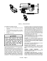
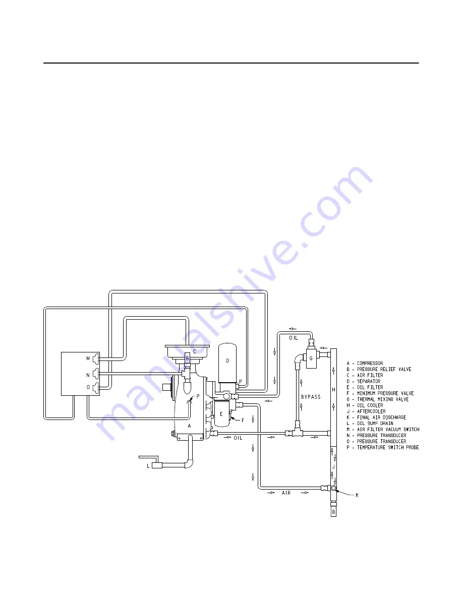
FIGURE 4–1 – CONTROL SCHEMATIC
201EBB797
(Ref. Drawing)
Summary of Contents for EBB BB-7.5 HP
Page 12: ...13 8 612 Page 2 FIGURE 1 2 PACKAGE COMPRESSOR MOTOR SIDE FIGURE 1 3 PACKAGE BELT GUARD SIDE...
Page 13: ...13 8 612 Page 3 FIGURE 1 4 PACKAGE CONTROLLER END...
Page 16: ...13 8 612 Page 6 DECALS 206EAQ077 212EAQ077 218EAQ077 211EAQ077 207EAQ077...
Page 17: ...13 8 612 Page 7 DECALS 216EAQ077 217EAQ077 222EAQ077 221EAQ077 208EAQ077...
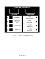
Page 32: ...13 8 612 Page 22 FIGURE 4 7 AUTO SENTRY S SOLID STATE CONTROL TOUCH PAD...
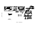
Page 33: ...13 8 612 Page 23 200EBB546 Ref Drawing FIGURE 4 8 WIRING DIAGRAM...
Page 53: ...13 8 612 Page 43 PIPING AND MOUNTING GROUP 213EBB810 B Ref Drawing...
Page 77: ...13 8 612 Page 67 INTEGRATED DRYER ASSEMBLY AND PIPING 301EBB810 A Ref Drawing...
Page 82: ...13 8 612 Page 72 300EBB541 B Ref Drawing...
Page 84: ......


