13–8–612 Page 21
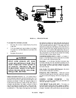
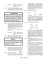
should read “0” pressure in the left window,
and –––– current sump temperature in the
right window.
Step 12: Move the circuit board slide switch back to
the “set” position (right). You may now pro-
ceed with normal start up procedure.
A.
To readjust, the slide switch
must be in the “+” position.
B.
If procedure is repeated, the
transducer zero operation may
be bypassed by not pressing
“Stop–Reset” while the dashes
(––– –––) are displayed.
C.
Transducer must be zeroed only
while at zero “0” pressure, or in-
valid shutdowns may occur.
LEAD–LAG OPERATION OF TWO COMPRES-
SORS – The Auto–Sentry S controller provides the ca-
pability of true lead–lag operation without the need to
purchase any additional equipment and without compli-
cated interconnecting wiring.
Follow these steps to operate two compressors in a
lead–lag arrangement:
Step 1:
Program load and unload pressure setpoint
on both units to the same value. For exam-
ple: Compressor “A” load at 92 PSI; unload
at 100 PSI. Compressor “B” load at 92 PSI;
unload at 100 PSI. See page 19, this section,
for complete information on programming
the setpoints.
Step 2:
Operate one compressor in the “Auto Lead”
mode. This compressor will now be the
“Lead” or “Base Load” compressor.
Step 3:
Operate the second compressor in the “Auto
Lag” mode. This compressor will now be the
“lag” or “trim” compressor. It will automatical-
ly be brought on line, if required, by a large air
demand. After the demand is satisfied, the
lag unit will unload, time out and stop, ready
to start again when needed.
Step 4:
Periodically reverse the roles of the units by
changing each unit’s mode of operation from
“Auto Lead” to “Auto Lag” and vice versa. By
using the hourmeters on the control panel to
schedule the mode changes, the operating
hours can be kept as close as possible,
equalizing machine wear and minimizing
maintenance costs.
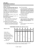
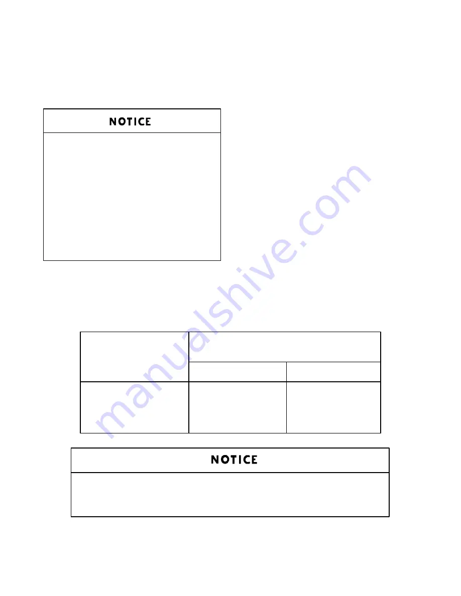
Load setpoint cannot be set within 8 psi of the unload setpoint.
Minimum operating pressure is 60 – 65 PSIG.
NAMEPLATE
CONTROL SYSTEM
FULL LOAD
PRESSURE (PSI)
OPERATING
PRESSURE
LOAD
UNLOAD
100
92
100
125
117
125
150
142
150
175
167
175
FIGURE 4–6 – MAXIMUM SETPOINTS FOR AUTO–SENTRY “S” CONTROLLER, PSIG
Summary of Contents for EBB BB-7.5 HP
Page 12: ...13 8 612 Page 2 FIGURE 1 2 PACKAGE COMPRESSOR MOTOR SIDE FIGURE 1 3 PACKAGE BELT GUARD SIDE...
Page 13: ...13 8 612 Page 3 FIGURE 1 4 PACKAGE CONTROLLER END...
Page 16: ...13 8 612 Page 6 DECALS 206EAQ077 212EAQ077 218EAQ077 211EAQ077 207EAQ077...
Page 17: ...13 8 612 Page 7 DECALS 216EAQ077 217EAQ077 222EAQ077 221EAQ077 208EAQ077...
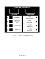
Page 32: ...13 8 612 Page 22 FIGURE 4 7 AUTO SENTRY S SOLID STATE CONTROL TOUCH PAD...
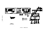
Page 33: ...13 8 612 Page 23 200EBB546 Ref Drawing FIGURE 4 8 WIRING DIAGRAM...
Page 53: ...13 8 612 Page 43 PIPING AND MOUNTING GROUP 213EBB810 B Ref Drawing...
Page 77: ...13 8 612 Page 67 INTEGRATED DRYER ASSEMBLY AND PIPING 301EBB810 A Ref Drawing...
Page 82: ...13 8 612 Page 72 300EBB541 B Ref Drawing...
Page 84: ......


