13–8–612 Page 34
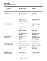
SYMPTOM
POSSIBLE CAUSE
REMEDY
Compressor is low on
3.
Intake controller is
3.
Adjust controller. See
delivery and pressure (continued).
incorrectly set.
Section 4, page 17.
4.
Minimum pressure valve
4.
Replace valve.
stuck closed.
High discharge air
1.
Thermostatic mixing
1.
Repair or replace valve.
temperature.
valve stuck open.
2.
Dirty or clogged cooler face.
2.
Clean cooler.
3.
Insufficient cooling
3.
Provide unrestricted supply
air flow.
of cooling air.
4.
Clogged oil filter or
4.
Replace filter or clean
cooler (interior).
cooler.
5.
Low compressor oil.
5.
Add oil to proper level.
6.
Fan motor fuses blown.
6.
Check wiring, replace fuses.
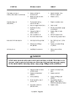
Excessive Oil Consumption
1.
Oil carryover through lines.
1.
See “Oil Carryover”, in this
section.
2.
Oil leaks at all fittings
2.
Tighten or replace fittings
and gaskets.
or gasket.
Oil Carry–Over
1.
Overfilling the reservoir.
1.
Drain excess oil from
system.
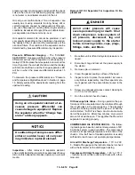
Air/oil under pressure will cause severe personal injury or death. Shut down com-
pressor, relieve system of all pressure, disconnect, tag and lockout power supply
to the starter before removing valves, caps, plugs, fittings, bolts, and filters.
2.
Clogged, broken or loose
2.
Tighten or replace faulty
oil return lines
lines.
3.
Ruptured oil separator
3.
Replace element.
element.
4.
Loose assembly.
4.
Tighten all fittings and
gaskets.
5.
Foam caused by use of
5.
Use Gardner Denver
R
incorrect oil.
AEON
t
2000, 4000 or
9000 SP Lubricating Coolant.
6.
Inoperative minimum
6.
Replace valve.
pressure valve.
Summary of Contents for EBB BB-7.5 HP
Page 12: ...13 8 612 Page 2 FIGURE 1 2 PACKAGE COMPRESSOR MOTOR SIDE FIGURE 1 3 PACKAGE BELT GUARD SIDE...
Page 13: ...13 8 612 Page 3 FIGURE 1 4 PACKAGE CONTROLLER END...
Page 16: ...13 8 612 Page 6 DECALS 206EAQ077 212EAQ077 218EAQ077 211EAQ077 207EAQ077...
Page 17: ...13 8 612 Page 7 DECALS 216EAQ077 217EAQ077 222EAQ077 221EAQ077 208EAQ077...
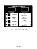
Page 32: ...13 8 612 Page 22 FIGURE 4 7 AUTO SENTRY S SOLID STATE CONTROL TOUCH PAD...
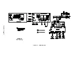
Page 33: ...13 8 612 Page 23 200EBB546 Ref Drawing FIGURE 4 8 WIRING DIAGRAM...
Page 53: ...13 8 612 Page 43 PIPING AND MOUNTING GROUP 213EBB810 B Ref Drawing...
Page 77: ...13 8 612 Page 67 INTEGRATED DRYER ASSEMBLY AND PIPING 301EBB810 A Ref Drawing...
Page 82: ...13 8 612 Page 72 300EBB541 B Ref Drawing...
Page 84: ......

