13–8–612 Page 36
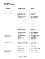
SYMPTOM
POSSIBLE CAUSE
REMEDY
“MOTOR OVERLOAD” (Continued)
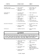
4.
Imbalanced amps.
4.
Rotate 3 phase power leads.
If the high reading stays on
the same leg, the problem is
with the motor.
If the high reading moves
with the lead, the problem
is with the incoming power.
5.
Incorrect motor overload
5.
Set overload to motor name–
setting.
plate amps.
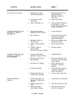
“CHANGE AIR FILTER” light on.
1.
Dirty air filter.
1.
Clean or replace.
“CHANGE AIR FILTER” light on,
1.
Loose connections.
1.
Clean and tighten
and WILL NOT RESET.
connections.
2.
Faulty vacuum switch.
2.
Measure the AC voltage
between wire number 7 and
wire number #6 at board.
If the reading is zero,
replace the vacuum switch.
2.
Control board fault.
2.
Measure the AC voltage
between wire number 7 and
wire number #6 at board.
If the reading is 24 volts,
replace the control board.
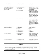
“MOTOR OVERLOAD”
1.
Loose connections.
1.
Measure the AC voltage
shutdown.
between wire number 5 and
(RELAY NOT TRIPPED)
wire number #6 at board.
If the reading is zero,
tighten the connections.
2.
Control board fault.
2.
Measure the AC voltage
between wire number 5 and
wire number #6 at board.
If the reading is 24 volts,
replace the control board.
“EO4”, Emergency Stop
1.
Loose connections or
1.
Tighten connection or
will not clear.
faulty switch.
repair or replace switch.
2.
Contact block not
2.
Ensure contact block is fully
properly installed.
snapped into left or right (not
center) slot of switch operator.
3.
Control board fault.
3.
Measure the AC voltage
between wire number 3 and
wire number #6 at board.
If the reading is 24 volts,
replace the control board.
Summary of Contents for EBB BB-7.5 HP
Page 12: ...13 8 612 Page 2 FIGURE 1 2 PACKAGE COMPRESSOR MOTOR SIDE FIGURE 1 3 PACKAGE BELT GUARD SIDE...
Page 13: ...13 8 612 Page 3 FIGURE 1 4 PACKAGE CONTROLLER END...
Page 16: ...13 8 612 Page 6 DECALS 206EAQ077 212EAQ077 218EAQ077 211EAQ077 207EAQ077...
Page 17: ...13 8 612 Page 7 DECALS 216EAQ077 217EAQ077 222EAQ077 221EAQ077 208EAQ077...
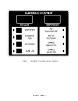
Page 32: ...13 8 612 Page 22 FIGURE 4 7 AUTO SENTRY S SOLID STATE CONTROL TOUCH PAD...
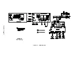
Page 33: ...13 8 612 Page 23 200EBB546 Ref Drawing FIGURE 4 8 WIRING DIAGRAM...
Page 53: ...13 8 612 Page 43 PIPING AND MOUNTING GROUP 213EBB810 B Ref Drawing...
Page 77: ...13 8 612 Page 67 INTEGRATED DRYER ASSEMBLY AND PIPING 301EBB810 A Ref Drawing...
Page 82: ...13 8 612 Page 72 300EBB541 B Ref Drawing...
Page 84: ......

