13–8–612 Page 60
SECTION 11
OPTIONAL INTEGRATED DRYER
SERVICE INSTRUCTIONS AND PARTS LIST
INSTALLATION – There should be at least 12 inches
(305 mm) clearance on all sides of the dryer. The con-
densor fins and surfaces should be regularly cleaned
with compressed air. The grill can be easily removed
to access the condensor coil. Ambient temperatures
should never be above 110
_
F (43
_
C) or below 40
_
F
(4
_
C).
Before start–up, the refrigerant suction pressure needs
to be read. This indicates the refrigerant pressure and
during shutdown corresponds with ambient tempera-
ture. See FIGURE 11–2.
At start–up, you will want to start the dryer prior to start-
ing the air compressor. DO NOT START WITH A
LOAD ON THE DRYER. After pushing the start button,
the “MOTOR RUN” indicating light will illuminate. The
dryer is designed to run continuously and must not by
cycled with the air compressor. The fan on the air
cooled unit will cycle in accordance with head pressure.
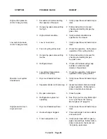
The refrigerant suction pressure gauge reading after
start–up and while operating under rated load will be
(R–22) 57–65 psig.
OPERATING INSTRUCTIONS – The EBB integrated
dryer is electrically isolated from the EBB air compres-
sor and will not cause a shutdown of an operating air
compressor if a fault condition should occur in the dry-
er.
The dryer unit requires a separate power source rated
at 120 VAC/60 Hz. Refer to the manufacturer’s name-
plate, on the dryer, for the minimum supply circuit con-
ductor ampacity and maximum rating of the branch–
circuit short–circuit and ground–fault protective device.
The dryer control circuit is internally fused for 2 ampere
protection. Additionally, the dryer compressor motor is
provided with internal thermal overload protection.
Externally mounted controls for the EBB integrated
dryer consist of a “START” pushbutton, “STOP” push-
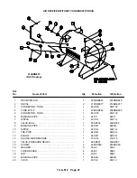
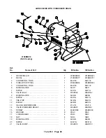
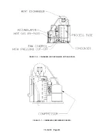
FIGURE 11–1 – COMPRESSOR WITH INTEGRATED DRYER
203EBB810–C
(Ref. Drawing)
Summary of Contents for EBB BB-7.5 HP
Page 12: ...13 8 612 Page 2 FIGURE 1 2 PACKAGE COMPRESSOR MOTOR SIDE FIGURE 1 3 PACKAGE BELT GUARD SIDE...
Page 13: ...13 8 612 Page 3 FIGURE 1 4 PACKAGE CONTROLLER END...
Page 16: ...13 8 612 Page 6 DECALS 206EAQ077 212EAQ077 218EAQ077 211EAQ077 207EAQ077...
Page 17: ...13 8 612 Page 7 DECALS 216EAQ077 217EAQ077 222EAQ077 221EAQ077 208EAQ077...
Page 32: ...13 8 612 Page 22 FIGURE 4 7 AUTO SENTRY S SOLID STATE CONTROL TOUCH PAD...
Page 33: ...13 8 612 Page 23 200EBB546 Ref Drawing FIGURE 4 8 WIRING DIAGRAM...
Page 53: ...13 8 612 Page 43 PIPING AND MOUNTING GROUP 213EBB810 B Ref Drawing...
Page 77: ...13 8 612 Page 67 INTEGRATED DRYER ASSEMBLY AND PIPING 301EBB810 A Ref Drawing...
Page 82: ...13 8 612 Page 72 300EBB541 B Ref Drawing...
Page 84: ......


