13–8–612 Page 65
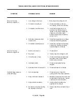
SYMPTOM
POSSIBLE CAUSE
REMEDY
High suction pressure
1.
Excessive air load exceeding
1.
Verify proper flow and load at dryer
(62 to 72 psig normal)
the capacity of the dryer.
inlet.
2.
Hot gas by–pass valve setting
2.
Follow instructions in manual
too high.
checking and setting hot gas by–
pass valve.
3.
High ambient condition.
3.
Verify ambient conditions as
specified in the manual.
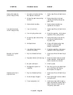
Low suction pressure
1.
Low or no air load.
1.
Verify proper flow and load at dryer
(62 to 72 psig normal)
inlet.
2.
Fan not cycling at low load.
2.
Check fan operation. Verify proper
operation of fan cycling control.
3.
Hot gas by–pass valve setting
3.
Follow instructions in manual for
too low.
checking and setting hot gas
by–pass valve.
4.
Refrigerant leak.
4.
Check unit for leaks using soap
bubbles or electronic leak
detector. Repair leak.
5.
Low ambient temperature
5.
Check fan operation. Verify proper
and fan not cycling.
operation of fan cycling control.
Moisture in air system
1.
Dryer overloaded (air flow).
1.
Verify proper flow and load at dryer
downstream.
inlet.
2.
Separator drains not functioning. 2.
Inspect automatic drain and verify
proper operation. Follow instruc–
tions in maintenance manual.
3.
By–pass valve open.
3.
Close by–pass.
4.
Refrigeration system not
4.
See “Dryer not running, Motor light
operating.
is on” and “Dryer not running,
Motor light is off,” page 64.
High pressure drop in
1.
Dryer overloaded (air flow).
1.
Verify proper flow and load at dryer
dryer air circuit.
inlet.
2.
Heat exchanger clogged.
2.
Clean exchanger to remove debris
and restart unit.
3.
Frozen evaporator coil.
3.
Verify proper load and hot gas by–
pass valve settings. Follow instruc–
tions in manual to check and set
hot gas by–pass valve.
Summary of Contents for EBB BB-7.5 HP
Page 12: ...13 8 612 Page 2 FIGURE 1 2 PACKAGE COMPRESSOR MOTOR SIDE FIGURE 1 3 PACKAGE BELT GUARD SIDE...
Page 13: ...13 8 612 Page 3 FIGURE 1 4 PACKAGE CONTROLLER END...
Page 16: ...13 8 612 Page 6 DECALS 206EAQ077 212EAQ077 218EAQ077 211EAQ077 207EAQ077...
Page 17: ...13 8 612 Page 7 DECALS 216EAQ077 217EAQ077 222EAQ077 221EAQ077 208EAQ077...
Page 32: ...13 8 612 Page 22 FIGURE 4 7 AUTO SENTRY S SOLID STATE CONTROL TOUCH PAD...
Page 33: ...13 8 612 Page 23 200EBB546 Ref Drawing FIGURE 4 8 WIRING DIAGRAM...
Page 53: ...13 8 612 Page 43 PIPING AND MOUNTING GROUP 213EBB810 B Ref Drawing...
Page 77: ...13 8 612 Page 67 INTEGRATED DRYER ASSEMBLY AND PIPING 301EBB810 A Ref Drawing...
Page 82: ...13 8 612 Page 72 300EBB541 B Ref Drawing...
Page 84: ......


