13--8--625
Page 12
7.
System Pressure -- The discharge pressure of
the unit is set at the factory. To change the dis-
charge pressure, set the controls to the desired
load pressure. DO NOT EXCEED THE MAXI-
MUM OPERATING PRESSURE ON THE COM-
PRESSOR NAMEPLATE. See Section 4, “Setting
the Load--Unload Pressure Setpoints,” for proce-
dure.
Operation at excessive discharge air
pressure can cause personal injury or
damage to equipment. Do not adjust
the full discharge air pressure above
the maximum stamped on the unit
nameplate.
8.
Operating Mode -- Refer to Section 4 for detailed
information on the control system.
9.
Enclosure -- Check for damaged panels or doors.
Check all screws and latches for tightness. Be
sure doors are closed and latched.
STARTING THE UNIT -- Observe the following starting
procedures.
The compressor starts and stops
automatically.
Automatic restarting
can cause injury or death. Open, tag
and lockout main disconnect and any
other circuits before servicing the
unit.
The enclosure doors must be in place
and fastened down to keep the com-
pressor package from overheating
when the compressor is running.
After an emergency stop, be sure that
the pressure in the air/oil reservoir is
less than 5 psig. Wait one minute or
more before restarting.
The controller has an automatic start/
stop sequence built in. You do NOT
need to close the air service valve.
Closing the air service valve on start--
up or prior to shutdown will cause
rapid cycling, and could cause a high
pressure shutdown.
1.
Turn the main switch on.
2.
Push the Start button.
DAILY CHECK -- Refer to Section 8, “Maintenance
Schedule,” page 39.
STOPPING THE UNIT:
1.
Push the Stop button.
2.
Wait one minute to allow the compressor to stop.
3.
Turn the main switch off.
EMERGENCY STOP -- The compressor stops when
the Emergency Stop button is pushed.
To restart the compressor, wait one (1) minute after
Emergency Stop, then turn the Emergency Stop button
clockwise to release it. Then, start the compressor per
the instructions above. If an alarm has been set, press
the Reset button before starting.
Summary of Contents for EFD-25 HP
Page 13: ...13 8 616 Page 4 DECALS 206EAQ077 212EAQ077 218EAQ077 211EAQ077 207EAQ077...
Page 14: ...13 8 616 Page 5 DECALS 216EAQ077 217EAQ077 222EAQ077 221EAQ077 208EAQ077...
Page 30: ...13 8 625 Page 21 FIGURE 4 4 COMPRESSOR RUNNING FULLY LOADED...
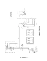
Page 32: ...13 8 625 Page 23 FIGURE 4 5 WIRING DIAGRAM 3 305865 Ref Drawing...
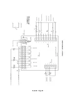
Page 33: ...13 8 625 Page 24 FIGURE 4 6 WIRING DIAGRAM 3 305979 A Ref Drawing...
Page 34: ...13 8 625 Page 25 FIGURE 4 7 WIRING DIAGRAM 3 305979 A Ref Drawing...
Page 54: ...13 8 625 Page 45 AIREND GROUP...
Page 60: ...13 8 625 Page 51 AIREND AND INLET FILTER ASSEMBLY...
Page 72: ...13 8 625 Page 63 COOLING GROUP...
Page 74: ...13 8 625 Page 65 CONTROL SYSTEM ASSEMBLY AND MOUNTING...
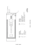
Page 78: ...13 8 625 Page 69 CONTROL BOX 3 305979 A Ref Drawing...


