13--8--625
Page 13
SECTION 4
CONTROLS & INSTRUMENTATION
GENERAL DESCRIPTION -- The rotary screw com-
pressor package is prewired with all controls, motor
and starter for the voltage and horsepower at the time
of ordering.It is necessary only to connect the com-
pressor unit to the correct power supply and the shop
air line. A standard compressor package consists of
the compressor, air/oil reservoir, oil cooling system and
filter, motor, starter/control box and control compo-
nents.
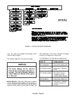
This compressor unit features the AIRPILOT ELEC-
TRONIC CONTROLLER, which integrates all the con-
trol functions under microprocessor control. Its func-
tions include safety and shutdown, compressor
regulation, operator control, and advisory/mainte-
nance indicators. The keypad and display provide the
operator with a logical and easily operated control of
the compressor package and indication of its condition.
AIRPILOT ELECTRONIC CONTROLLER Descrip-
tion of Operation -- The controller controls all the func-
tions connected to the regulation of the compressor.
The unit adjusts the following parameters of the
compressor’s operation:
Discharge pressure regulating method:
blow-
down/stopping automatics, start/stop operation.
Unload pressure: the pressure at which the com-
pressor unloads.
Discharge pressure:
the pressure at which the
compressor goes from unload to full output.
High discharge temperature shutdown operation.
High pressure shutdown operation.
Compressor motor wye delta starting time.
Compressor automatic time delay before shutting
down (air/oil separator is blowndown first)
Drain time and interval for water separator.
Compressor blowdown time before restart. (The
air/oil separator must be blowndown before
starting)
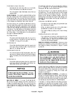
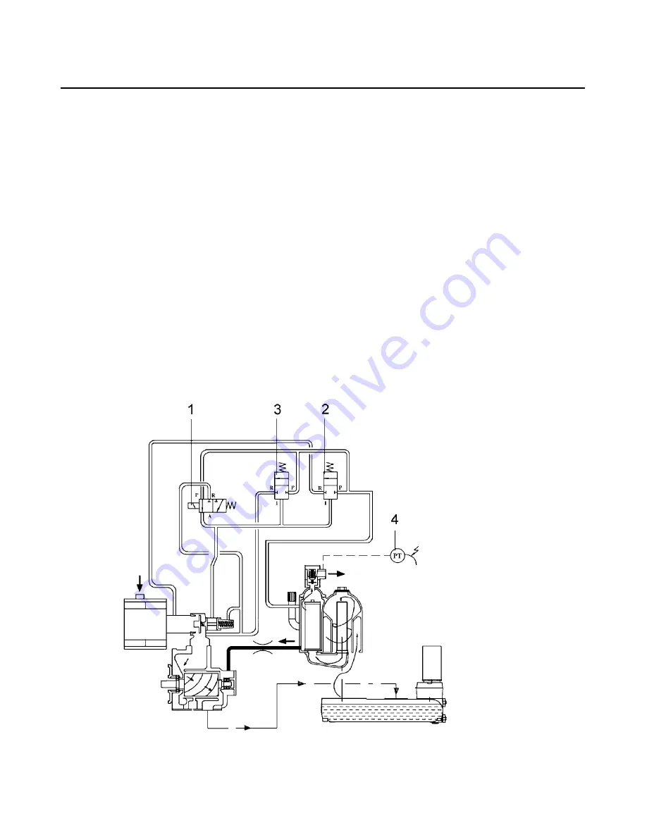
Control System Operation -- The purpose of the con-
trol system is to adjust the production of compressed
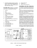
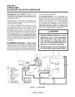
FIGURE 4--1 -- CONTROL SCHEMATIC
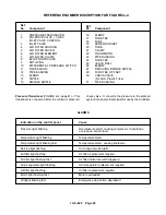
Ref.
No.
Description
1
Inlet Valve Solenoid
2
Blowdown Valve
3
Purge Valve
4
Pressure Transducer
Summary of Contents for EFD-25 HP
Page 13: ...13 8 616 Page 4 DECALS 206EAQ077 212EAQ077 218EAQ077 211EAQ077 207EAQ077...
Page 14: ...13 8 616 Page 5 DECALS 216EAQ077 217EAQ077 222EAQ077 221EAQ077 208EAQ077...
Page 30: ...13 8 625 Page 21 FIGURE 4 4 COMPRESSOR RUNNING FULLY LOADED...
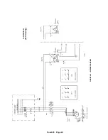
Page 32: ...13 8 625 Page 23 FIGURE 4 5 WIRING DIAGRAM 3 305865 Ref Drawing...
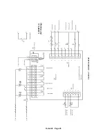
Page 33: ...13 8 625 Page 24 FIGURE 4 6 WIRING DIAGRAM 3 305979 A Ref Drawing...
Page 34: ...13 8 625 Page 25 FIGURE 4 7 WIRING DIAGRAM 3 305979 A Ref Drawing...
Page 54: ...13 8 625 Page 45 AIREND GROUP...
Page 60: ...13 8 625 Page 51 AIREND AND INLET FILTER ASSEMBLY...
Page 72: ...13 8 625 Page 63 COOLING GROUP...
Page 74: ...13 8 625 Page 65 CONTROL SYSTEM ASSEMBLY AND MOUNTING...
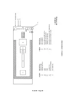
Page 78: ...13 8 625 Page 69 CONTROL BOX 3 305979 A Ref Drawing...


