13--8--625
Page 14
air according to the demands of the system and to
lower power consumption.
Compressor Running Fully Loaded (FIGURE 4--1,
page 13) --When the compressor runs loaded, the inlet
valve is open and the compressor produces com-
pressed air.
As the compressor package starts, the motor is
switched from wye to delta, the inlet control solenoid
valve ( 1 ) is energized. This opens a connection be-
tween the unit’s inlet and the back side of the inlet valve
piston. A partial vacuum on the inlet valve plate and
piston cracks open the inlet valve and the compressor
starts producing compressed air. When the pressure
in the air/oil separator increases, the pressure on the
front side of the piston opens the valve completely, and
the compressor runs at full capacity.
Compressor Running Unloaded (FIGURE 4--1,
page 13) -- When the compressor is running unloaded,
the inlet valve is closed and the compressor produces
no compressed air. At the same time, to minimize pow-
er consumption, the air/oil separator is blown down.
When the discharge pressure reaches the unload pres-
sure programmed into the controller, the inlet control
solenoid valve ( 1 ) opens the connection between the
back side of the inlet piston and the air/oil reservoir, and
the inlet valve spring closes the inlet valve plate.
At the same time, the blowdown valve ( 2 ) opens and
the air/oil reservoir is blown down. The purge valve (3)
is used for bleeding a small amount of air back into the
inlet side of the compressor. This lowers the noise the
compressor makes when running in the unloaded
condition.
Automatic Start/Stop -- If demand for compressed air
stops, the compressor runs unloaded and blown down
until the automatic timer has counted down, then the
unit shuts down. When the demand for compressed air
rises enough to drop the pressure below the load pres-
sure programmed into the controller, the compressor
automatically starts.
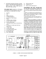
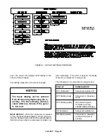
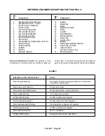
STARTER/CONTROL BOX (FIGURE 4--2, page 15) --
The following parameters of the compressors opera-
tion can be adjusted:
1.
Unloading Pressure -- the pressure at which the
compressor unloads (upper limit).
2.
Load Pressure -- the pressure at which the com-
pressor loads (lower limit).
3.
Compressor Automatic Timer (Time the unit runs
unloaded before the motor stops.
4.
Automatic Start after power shutdown.
5.
Condensate Removal open time.
6.
Condensate Removal close time.
The AIRPILOT ELECTRONIC CONTROLLER has a
7--digit LED display for showing information. The nor-
mal display shows operating pressure and tempera-
ture.
The electronic controller has a built--in automatic re-
start for restarting the compressor package after a
power failure. This function is switched off in the facto-
ry settings. See USER MENU, Automatic start after
power failure in this section, page 17.
The version identification of the electronic controller is
on a label behind the controller and on the display when
the controller is powered up.
AIRPILOT ELECTRONIC CONTROL OPERATION --
Normal starting and stopping the compressor package
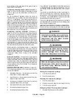
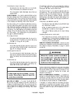
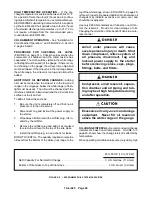
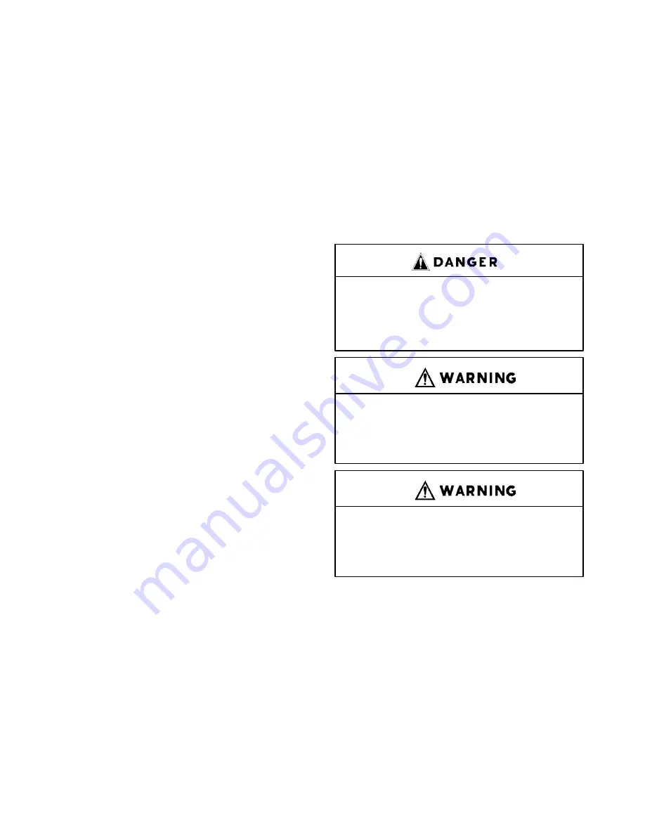
Automatic restarting can cause injury
or death. Open, tag and lockout main
disconnect and any other circuits
before servicing the unit.
The enclosure doors must be in place
and fastened down to keep the com-
pressor package from overheating
when the compressor is running.
After an emergency stop, be sure that
the pressure in the air/oil reservoir is
less than 5 psig. Wait one minute or
more before restarting.
Starting the compressor package:
1.
Turn the main switch on.
2.
Push the start button.
Stopping the compressor package:
1.
Push the stop button.
2.
Wait one minute to allow the compressor to stop.
3.
Turn the main switch off.
Emergency Stop of the compressor package:
1.
Depress the Emergency Stop button.
Summary of Contents for EFD-25 HP
Page 13: ...13 8 616 Page 4 DECALS 206EAQ077 212EAQ077 218EAQ077 211EAQ077 207EAQ077...
Page 14: ...13 8 616 Page 5 DECALS 216EAQ077 217EAQ077 222EAQ077 221EAQ077 208EAQ077...
Page 30: ...13 8 625 Page 21 FIGURE 4 4 COMPRESSOR RUNNING FULLY LOADED...
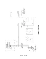
Page 32: ...13 8 625 Page 23 FIGURE 4 5 WIRING DIAGRAM 3 305865 Ref Drawing...
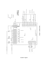
Page 33: ...13 8 625 Page 24 FIGURE 4 6 WIRING DIAGRAM 3 305979 A Ref Drawing...
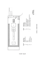
Page 34: ...13 8 625 Page 25 FIGURE 4 7 WIRING DIAGRAM 3 305979 A Ref Drawing...
Page 54: ...13 8 625 Page 45 AIREND GROUP...
Page 60: ...13 8 625 Page 51 AIREND AND INLET FILTER ASSEMBLY...
Page 72: ...13 8 625 Page 63 COOLING GROUP...
Page 74: ...13 8 625 Page 65 CONTROL SYSTEM ASSEMBLY AND MOUNTING...
Page 78: ...13 8 625 Page 69 CONTROL BOX 3 305979 A Ref Drawing...


