13--8--625
Page 16
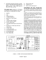
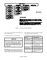
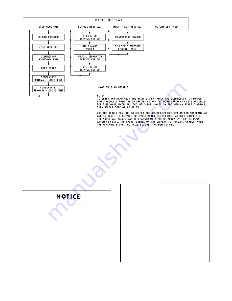
FIGURE 4--3 -- AIR PILOT ELECTRONIC CONTROLLER
306EAU1255--A
(Ref. Drawing)
keys. The value on the display starts flashing to indi-
cate it is being changed.
The flashing stops when the value is changed.
The basic display can be entered
from all menus by depressing the re-
set key. The basic display will also
return after one minute, if the panel
is not used.
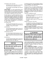
BASIC DISPLAY -- When the compressor is switched
on, the unit shows the basic display. If the motor is run-
ning, the display shows a dot and the output pressure
(the dot is shown when the compressor is loaded, not
when unloading). If the motor is stopped, the display
shows the compressor’s running mode.
The following are the compressor running modes:
DISPLAY
RUNNING MODE
OFF illuminated
Compressor switched off
OFF flashing slowly
Compressor in blowdown
mode
OFF flashing quickly
Stop command given,
compressor running
unloaded before stopping.
ON illuminated
Compressor switched on
ON flashing quickly
Compressor in automatic
mode and can start at
any time.
Summary of Contents for EFD-25 HP
Page 13: ...13 8 616 Page 4 DECALS 206EAQ077 212EAQ077 218EAQ077 211EAQ077 207EAQ077...
Page 14: ...13 8 616 Page 5 DECALS 216EAQ077 217EAQ077 222EAQ077 221EAQ077 208EAQ077...
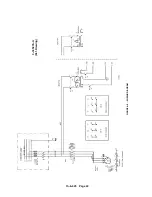
Page 30: ...13 8 625 Page 21 FIGURE 4 4 COMPRESSOR RUNNING FULLY LOADED...
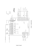
Page 32: ...13 8 625 Page 23 FIGURE 4 5 WIRING DIAGRAM 3 305865 Ref Drawing...
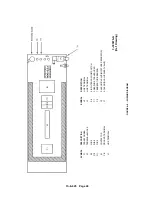
Page 33: ...13 8 625 Page 24 FIGURE 4 6 WIRING DIAGRAM 3 305979 A Ref Drawing...
Page 34: ...13 8 625 Page 25 FIGURE 4 7 WIRING DIAGRAM 3 305979 A Ref Drawing...
Page 54: ...13 8 625 Page 45 AIREND GROUP...
Page 60: ...13 8 625 Page 51 AIREND AND INLET FILTER ASSEMBLY...
Page 72: ...13 8 625 Page 63 COOLING GROUP...
Page 74: ...13 8 625 Page 65 CONTROL SYSTEM ASSEMBLY AND MOUNTING...
Page 78: ...13 8 625 Page 69 CONTROL BOX 3 305979 A Ref Drawing...


