13--8--625
Page 17
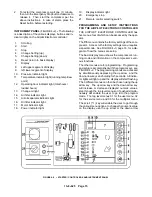
Use the scroll key (
) to get the following information:
DISPLAY
RUNNING MODE
Pressure light on
(1)
Discharge pressure
Temperature light on
(2)
Compressor temperature
Operating hours light
Operating hours
on
(3)
Operating hours
Loaded hours flashing
flashing
(3)
Change Oil light on
(4)
Change oil
Air filter light on
(5)
Replace air filter
Oil separator light on
(6)
Replace air/oil separator
Oil filter light on
(7)
Replace oil filter
No lights on
Compressor running mode
on display
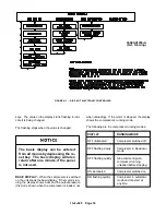
USER MENU -- To enter the User Menu from the basic
display when the compressor is stopped, simul-
taneously push the up arrow and the down arrow keys
and hold for 5 seconds, until all the indicator lights on
the display start flashing, then select code 01.
Use the scroll key (
) to select the desired option for
programming. The numerical values can be changed
with the up arrow or the down arrow keys. The value
flashes on the display to indicate change. When the
flashing stops, the value becomes the new setting.
The following can be programmed through the User
Menu.
Setting the unload pressure:
The pressure indicator light and the upper left seg-
ment of the display illuminate when the unload
pressure is in the programming mode.
The discharge pressure shifts as the unload pres-
sure is changed (the pressure differential remains
constant).
The unload pressure set at the factory is equal to
the compressor’s maximum pressure which can-
not be exceeded.
Setting the discharge pressure:
The pressure indicator light and the lower left seg-
ment of the display illuminate when the discharge
pressure is in the programming mode.
Changing the discharge pressure
will cause the pressure difference to
change.
Compressor automatic timer:
The automatic timer determines how long the
compressor runs unloaded before stopping.
The operating hour light illuminates when the un-
loading time is programmable. This timer is facto-
ry set at 5 minutes.
Automatic start after power failure:
This mode is disabled by setting the value to 0.
Other values define the starting delay of the com-
pressor when power is restored, recommend one
(1) minute or longer.
The operating light flashes when automatic start-
ing is programmable.
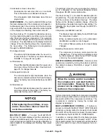
Automatic restarting can cause injury
or death. Open, tag and lockout main
disconnect and any other circuits
before servicing the unit.
Condensate removal, open time:
Condensate removal open time is in seconds.
The air filter light illuminates when this can be pro-
grammed.
Too short condensate removal time
at too long an interval may cause wa-
ter to enter the network. Humid and
warm intake air require longer and
more frequent condensate removal.
Too long of a condensate removal
time at too short an interval will
waste compressed air.
Summary of Contents for EFD-25 HP
Page 13: ...13 8 616 Page 4 DECALS 206EAQ077 212EAQ077 218EAQ077 211EAQ077 207EAQ077...
Page 14: ...13 8 616 Page 5 DECALS 216EAQ077 217EAQ077 222EAQ077 221EAQ077 208EAQ077...
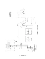
Page 30: ...13 8 625 Page 21 FIGURE 4 4 COMPRESSOR RUNNING FULLY LOADED...
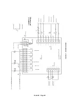
Page 32: ...13 8 625 Page 23 FIGURE 4 5 WIRING DIAGRAM 3 305865 Ref Drawing...
Page 33: ...13 8 625 Page 24 FIGURE 4 6 WIRING DIAGRAM 3 305979 A Ref Drawing...
Page 34: ...13 8 625 Page 25 FIGURE 4 7 WIRING DIAGRAM 3 305979 A Ref Drawing...
Page 54: ...13 8 625 Page 45 AIREND GROUP...
Page 60: ...13 8 625 Page 51 AIREND AND INLET FILTER ASSEMBLY...
Page 72: ...13 8 625 Page 63 COOLING GROUP...
Page 74: ...13 8 625 Page 65 CONTROL SYSTEM ASSEMBLY AND MOUNTING...
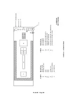
Page 78: ...13 8 625 Page 69 CONTROL BOX 3 305979 A Ref Drawing...


