13--8--625
Page 18
Condensate removal, close time:
Condensate removal close time is in seconds.
This is time between condensate removal.
The oil separator light illuminates when this can
programmed.
SERVICE MENU -- To enter the SERVICE Menu from
the basic display when the compressor is stopped, si-
multaneously push the up arrow and the down arrow
keys and hold for 5 seconds, until all the indicator lights
on the display start flashing, then select code 02.
Use the scroll key (
) to select the desired service op-
tion for programming and to reset the service intervals
after the service has been completed. The numerical
values can be changed with the up arrow or the down
arrow keys. The value flashes on the display to indicate
change. When the flashing stops, the value becomes
the new setting. The following can be programmed
through the SERVICE MENU.
Oil change interval:
The service light illuminates when the new oil in-
terval can be set. The factory recommends using
FIGURE 5--3, page 29, as a guide.
Air filter interval:
The air filter light illuminates when the new service
interval can be set for the air filter. See Section 6,
page 35, for change intervals.
Air/oil separator interval:
The air/oil separator light illuminates when the
new service interval can be set for the air/oil sepa-
rator. The factory recommends this be set at 4000
hours.
Oil filter interval:
The oil filter light illuminates when the new service
interval can be set for the oil filter. The factory rec-
ommends this be set at 1000 hours.
After replacing the oil, filters, or sep-
arator, the service interval must be
set in the controller.
MULTIPILOT MENU -- To enter the MULTIPILOT
Menu from the basic display when the compressor is
stopped, simultaneously push the up arrow and the
down arrow keys and hold for 5 seconds, until all the in-
dicator lights on the display start flashing, then select
code 03.
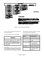
The settings in this menu are used when the compres-
sor is connected to the optional Multipilot control
through an RS 485 communication line.
Use the scroll key (
) to select the desired option for
programming. The numerical values can be changed
with the up arrow or the down arrow keys. The value
flashes on the display to indicate change. When the
flashing stops, the value becomes the new setting. The
following can be programmed through the MULTIPI-
LOT MENU.
Compressor identification number:
The display shows alternately the text RS 485 and
the compressor number.
When no indicator lights are on, the compressor
identification number can be changed.
The number flashes quickly as its value is being
changed.
Selecting the pressure control point:
The compressor’s pressure control point can be
changed here. The text LOCAL indicates control
by the compressor, while the text PILOT means
control by the multipilot system.
REMOTE CONTROL OPERATION -- Remote control
operation is selected by turning the selector switch on
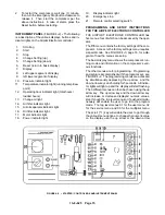
the cabinet clockwise, FIGURE 4--2, page 15, detail
number 21.
When the remote control is enabled,
the compressor’s own start button is
not in operation. However, the com-
pressor can be stopped with the stop
button on the compressor.
In the remote control mode the compressor is operated
with a closing contact which is connected to terminal
blocks 22 and 30 of the compressor control box. The
compressor is started by closing the contact and
stopped by opening it.
MULTI--COMPRESSOR CONTROL -- If multi--com-
pressor control with the MULTIPILOT CONTROLLER
is desired, a closing contact is connected to terminals
20 and 25. When the contact is closed, the compressor
is controlled by the MULTIPILOT CONTROLLER.
In addition, a closing contact for discharge pressure
regulation is connected to terminals 21 and 27. When
the contact is closed, the compressor runs fully loaded;
when the contact is open, the compressor runs un-
loaded.
Summary of Contents for EFD-25 HP
Page 13: ...13 8 616 Page 4 DECALS 206EAQ077 212EAQ077 218EAQ077 211EAQ077 207EAQ077...
Page 14: ...13 8 616 Page 5 DECALS 216EAQ077 217EAQ077 222EAQ077 221EAQ077 208EAQ077...
Page 30: ...13 8 625 Page 21 FIGURE 4 4 COMPRESSOR RUNNING FULLY LOADED...
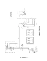
Page 32: ...13 8 625 Page 23 FIGURE 4 5 WIRING DIAGRAM 3 305865 Ref Drawing...
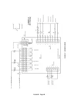
Page 33: ...13 8 625 Page 24 FIGURE 4 6 WIRING DIAGRAM 3 305979 A Ref Drawing...
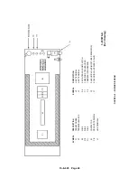
Page 34: ...13 8 625 Page 25 FIGURE 4 7 WIRING DIAGRAM 3 305979 A Ref Drawing...
Page 54: ...13 8 625 Page 45 AIREND GROUP...
Page 60: ...13 8 625 Page 51 AIREND AND INLET FILTER ASSEMBLY...
Page 72: ...13 8 625 Page 63 COOLING GROUP...
Page 74: ...13 8 625 Page 65 CONTROL SYSTEM ASSEMBLY AND MOUNTING...
Page 78: ...13 8 625 Page 69 CONTROL BOX 3 305979 A Ref Drawing...


