13--8--625
Page 28
HIGH TEMPERATURE OPERATION -- If the dis-
charge temperature is sustained between 200--210
_
F
for a period of more than four (4) hours due to continu-
ing high ambient air temperature, use Gardner Denver-
AEON 9000SP Lubricating Coolant which is a superior
synthetic lubricant. Short periods of up to four (4) hours
of sustained discharge temperatures up to 210
_
F do
not require a change from the recommended year--
round lubricant AEON 4000.
COLD AMBIENT OPERATION -- See “Installation for
Cold Weather Operation,” and FIGURE 2--5, Section
2, pages 8 and 9.
PROCEDURE
FOR
CHECKING
OIL
LEVEL
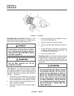
(FIGURE 5--4, page 31) -- Check the oil level when the
compressor is shutdown and the oil/air mixture has
separated. The oil should be visible in the white range
(a flashlight must be used) of the gauge. If there is only
red showing on the gauge, the oil level is too high and
must be drained. If the oil level is in the red range below
the white range, the oil level is too low and oil must be
added.
ADDITION OF OIL BETWEEN CHANGES -- Adding
oil must be made when the oil level is in the lower red
range on the oil gauge, below the white range (a flash-
light must be used). The oil must be checked with the
machine shutdown, blown down and the air/oil mixture
settled out to air and oil.
To add oil, follow these steps:
1.
Be sure the unit is completely off and that no air
pressure is in the oil reservoir.
2.
Disconnect, tag and lockout the power supply to
the starter.
3.
Wipe away all dirt around the oil filler plug. It is lo-
cated by the oil filter.
4.
Remove the oil filler plug and add oil as required
to return the oil level to the top of the site glass.
5.
Install the oil filler plug, run and check for leaks.
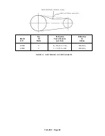
DO NOT OVERFILL . The quantity required to raise the
oil level from the bottom of the white (run) range to the
top of the white range, shown in FIGURE 5--2, page 28,
is three (3) quarts. Repeated addition of oil between oil
changes may indicate excessive oil carry--over and
should be investigated.
Use only CLEAN containers and funnels so no dirt en-
ters the reservoir. Provide for clean storage of oils.
Changing the oil will be of little benefit if done in a care-
less manner.
Air/oil under pressure will cause
severe personal injury or death. Shut
down compressor, relieve system of
all pressure, disconnect, tag and
lockout power supply to the starter
before removing valves, caps, plugs,
fittings, bolts, and filters.
Compressor, air/oil reservoir, separa-
tion chamber and all piping and tub-
ing may be at high temperature during
and after operation.
Excessive oil carry--over can damage
equipment.
Never fill oil reservoir
above the white range on the gauge.
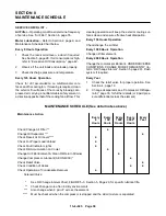
OIL CHANGE INTERVAL -- Recommended oil change
intervals are based on oil temperature. FIGURE 5--3,
page 29, shows how the change interval is affected by
temperature.
When operating conditions are severe (very dusty, high
25 to 50 HP (19 to 37 KW)
Refill Capacity For Normal Oil Change
3 U.S. Gallons (11 Liters)
. . . . . . . . . . . . . . . . . . . . . . . . . . . . . . . . . .
Bottom of Site Glass to Top of Site Glass
3 U.S. Quart (3 Liters)
. . . . . . . . . . . . . . . . . . . . . . . . . . . . . . . . . .
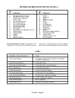
FIGURE 5--2 -- APPROXIMATE OIL SYSTEM CAPACITIES
Summary of Contents for EFD-25 HP
Page 13: ...13 8 616 Page 4 DECALS 206EAQ077 212EAQ077 218EAQ077 211EAQ077 207EAQ077...
Page 14: ...13 8 616 Page 5 DECALS 216EAQ077 217EAQ077 222EAQ077 221EAQ077 208EAQ077...
Page 30: ...13 8 625 Page 21 FIGURE 4 4 COMPRESSOR RUNNING FULLY LOADED...
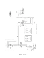
Page 32: ...13 8 625 Page 23 FIGURE 4 5 WIRING DIAGRAM 3 305865 Ref Drawing...
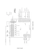
Page 33: ...13 8 625 Page 24 FIGURE 4 6 WIRING DIAGRAM 3 305979 A Ref Drawing...
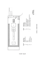
Page 34: ...13 8 625 Page 25 FIGURE 4 7 WIRING DIAGRAM 3 305979 A Ref Drawing...
Page 54: ...13 8 625 Page 45 AIREND GROUP...
Page 60: ...13 8 625 Page 51 AIREND AND INLET FILTER ASSEMBLY...
Page 72: ...13 8 625 Page 63 COOLING GROUP...
Page 74: ...13 8 625 Page 65 CONTROL SYSTEM ASSEMBLY AND MOUNTING...
Page 78: ...13 8 625 Page 69 CONTROL BOX 3 305979 A Ref Drawing...

