13--8--625
Page 33
the oil system, remove the mixing valve and clean all
parts thoroughly.
OIL RESERVOIR -- The oil reservoir--separator com-
bines multiple functions into one vessel. The lower half
is the oil reservoir, providing oil storage capacity for the
system and the top portion, a primary oil separation
means. The reservoir also provides limited air storage
for control and gauge actuation.
COMPRESSOR AIR/OIL SEPARATOR located in a
separate housing, consists of a renewable cartridge--
type separator element and provides the final removal
of oil from the air stream.
Oil impinging on the inside of the separator element
drains directly back into the oil reservoir by gravity. Oil
collected outside the element is returned through tub-
ing to the compressor cylinder.
Oil carry--over through the service lines may be caused
by a faulty oil separator, overfilling of the oil reservoir,
oil that foams, oil return line malfunction, or water con-
densate in the oil. If oil carryover occurs, inspect the
separator only after it is determined that the oil level is
not too high, the oil is not foaming excessively, the oil
return tube from the bottom of the separator to the com-
pressor cylinder is not clogged or pinched off, the check
valve in the oil return is functioning properly, and there
is not water or an oil/water emulsion in the oil.
Oil carry--over malfunctions of the oil separator are
usually due to using elements too long, heavy dirt or
varnish deposits caused by inadequate air filter ser-
vice, use of improper oil, or using oil too long for existing
conditions. Excessive tilt angle of the unit will also ham-
per separation and cause oil carry--over.
Oil separator element life cannot be predicted; it will
vary greatly depending on the conditions of operation,
the quality of the oil used and the maintenance of the
oil and air filters. The condition of the separator can be
determined by pressure differential or by inspection.
Pressure Differential Gauging
1.
Be sure the unit is completely off and that no air
pressure is in the oil reservoir.
2.
Disconnect, tag and lockout the power supply to
the starter.
3.
Install accurate pressure gauges upstream and
downstream of the air/oil separator.
4.
If the differential pressure is greater than 8 psi (.6
bar), change the air/oil separator, see “Removal of
Oil Separator For Inspection or Replacement”.
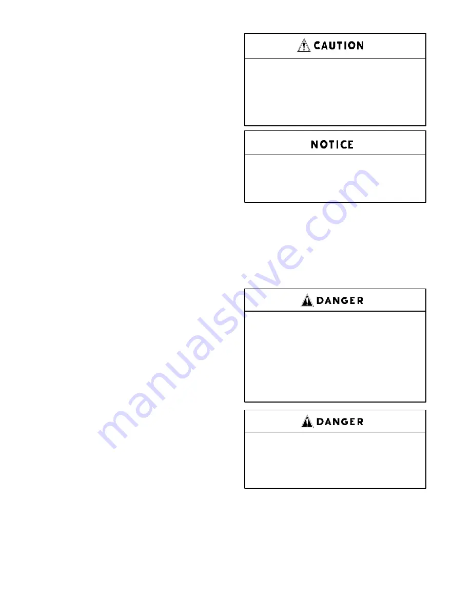
Using an oil separator element at ex-
cessive
pressure
differential
can
cause damage to equipment. Replace
the separator when the “Change Sep-
arator” advisory appears.
A sudden drop of zero pressure differ-
ential or sudden heavy oil carryover
may indicate a ruptured element.
Inspection -- After removal of separator element,
shine a light inside the element to reveal areas of heavy
dirt or varnish deposits or breaks (ruptures) in element
media.
Removal of Oil Separator For Inspection or Re-
placement:
Air/oil under pressure will cause
severe personal injury or death. Shut
down compressor, relieve system of
all pressure, disconnect, tag and
lockout power supply to the starter
before removing valves, caps, plugs,
fittings, bolts, and filters.
Compressor, air/oil reservoir, separa-
tion chamber and all piping and tub-
ing may be at high temperature during
and after operation.
1.
Be certain the unit is off and that no air pressure
is in the oil reservoir. The compressor package
will automatically blowdown in about 2 minutes.
2.
Close the air service valve located after the com-
pressor package discharge.
Summary of Contents for EFD-25 HP
Page 13: ...13 8 616 Page 4 DECALS 206EAQ077 212EAQ077 218EAQ077 211EAQ077 207EAQ077...
Page 14: ...13 8 616 Page 5 DECALS 216EAQ077 217EAQ077 222EAQ077 221EAQ077 208EAQ077...
Page 30: ...13 8 625 Page 21 FIGURE 4 4 COMPRESSOR RUNNING FULLY LOADED...
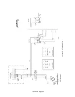
Page 32: ...13 8 625 Page 23 FIGURE 4 5 WIRING DIAGRAM 3 305865 Ref Drawing...
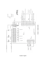
Page 33: ...13 8 625 Page 24 FIGURE 4 6 WIRING DIAGRAM 3 305979 A Ref Drawing...
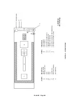
Page 34: ...13 8 625 Page 25 FIGURE 4 7 WIRING DIAGRAM 3 305979 A Ref Drawing...
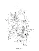
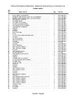
Page 54: ...13 8 625 Page 45 AIREND GROUP...
Page 60: ...13 8 625 Page 51 AIREND AND INLET FILTER ASSEMBLY...
Page 72: ...13 8 625 Page 63 COOLING GROUP...
Page 74: ...13 8 625 Page 65 CONTROL SYSTEM ASSEMBLY AND MOUNTING...
Page 78: ...13 8 625 Page 69 CONTROL BOX 3 305979 A Ref Drawing...


