13--8--625
Page 35
SECTION 6
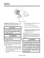
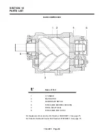
AIR FILTER
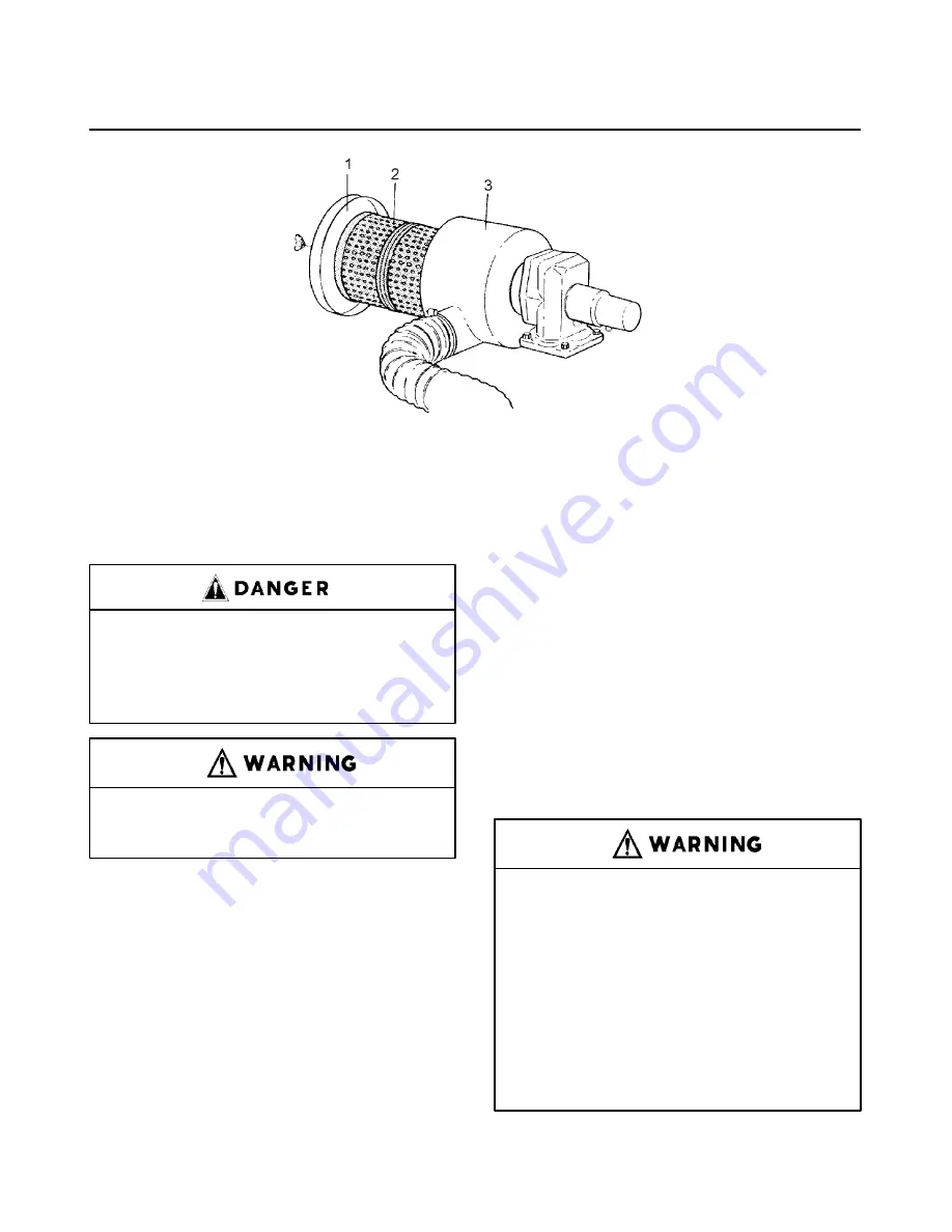
FIGURE 6--1 -- AIR FILTER
STANDARD DUTY AIR FILTER (FIGURE 6--1) -- Re-
placement instructions are given in the following sec-
tions: Filter Element and Filter Element Life.
Compressor, air/oil reservoir, separa-
tion chamber and all piping and tub-
ing may be at high temperature during
and after operation.
The air filter element can not be
cleaned or reused.
Filter Element -- The element should be replaced
when inspection indicates an accumulation of dirt on
the outside of the element. Inspect every few days until
experience determines the proper time interval for
servicing.
To Service:
1.
Be certain the unit is off and that no air pressure
is in the air/oil reservoir. The compressor package
will automatically blow down in about 2 minutes.
2.
Close the air service valve located after the com-
pressor package discharge.
3.
Disconnect, tag and lockout the power supply to
the starter.
4.
Remove the air filter cover (FIGURE 6--1) and re-
move the old filter elements.
5.
Clean the inside of the air filter housing.
6.
Install new air filter elements and the air filter cov-
er.
7.
Change the setting in the electronic controller to
correspond with a new filter (see Section 4). Do
not set higher than 2000 hours.
8.
Open the air service valve.
Filter Element Life -- The element should be replaced
if visual inspection indicates an accumulation of dirt, or
a rupture, crack or pin hole in the pleated media. In-
spection should be done by placing a bright light inside
the element.
Do not oil this element. Never operate
unit without element. Never use ele-
ments that are damaged or ruptured.
Never use elements that won’t seal.
Never use element more than 2000
hours. Keep spare elements on hand
to reduce downtime. Store elements
in a protected area free from damage,
dirt and moisture. Handle filter ele-
ments with care.
Summary of Contents for EFD-25 HP
Page 13: ...13 8 616 Page 4 DECALS 206EAQ077 212EAQ077 218EAQ077 211EAQ077 207EAQ077...
Page 14: ...13 8 616 Page 5 DECALS 216EAQ077 217EAQ077 222EAQ077 221EAQ077 208EAQ077...
Page 30: ...13 8 625 Page 21 FIGURE 4 4 COMPRESSOR RUNNING FULLY LOADED...
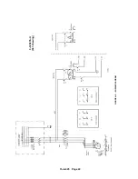
Page 32: ...13 8 625 Page 23 FIGURE 4 5 WIRING DIAGRAM 3 305865 Ref Drawing...
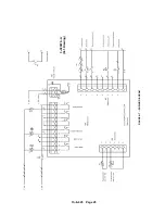
Page 33: ...13 8 625 Page 24 FIGURE 4 6 WIRING DIAGRAM 3 305979 A Ref Drawing...
Page 34: ...13 8 625 Page 25 FIGURE 4 7 WIRING DIAGRAM 3 305979 A Ref Drawing...
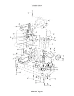
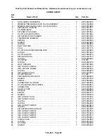
Page 54: ...13 8 625 Page 45 AIREND GROUP...
Page 60: ...13 8 625 Page 51 AIREND AND INLET FILTER ASSEMBLY...
Page 72: ...13 8 625 Page 63 COOLING GROUP...
Page 74: ...13 8 625 Page 65 CONTROL SYSTEM ASSEMBLY AND MOUNTING...
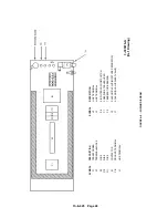
Page 78: ...13 8 625 Page 69 CONTROL BOX 3 305979 A Ref Drawing...


